Derui chamber
Motorcycle wheels are subjected to enormous torsional and bending stresses during everyday riding. Every corner, every pothole impact, and every acceleration event transfers complex loads through the wheel rim, spokes, and hub. Over time, these repeated stress cycles can initiate micro-cracks that propagate silently until sudden wheel failure occurs. This is precisely why the international standard ISO 8644 exists — it defines the testing methodology that every motorcycle wheel manufacturer must follow to prove their products are safe for real-world service.
Key Takeaways
- ECE R.62, ISO 4209, and UN Regulation No. 78 set the mandatory safety and performance benchmarks for motorcycle frame and component testing.
- Fatigue testing protocols require a minimum of 100,000 load cycles at specified force magnitudes to simulate multi-year real-world usage.
- Drop impact testing evaluates frame integrity at defined heights — typically 300-500 mm — to simulate crash scenarios and curb impacts.
- Steering head strength and torsion tests verify handling stability under extreme cornering loads encountered in sport and adventure riding.
- Exhaust system durability testing ensures compliance with noise emission regulations and vibration resistance across 5,000+ hours of operation.
In this comprehensive technical guide, we break down the ISO 8644 motorcycle wheel torsional fatigue testing procedure from start to finish. Whether you are a quality engineer setting up a testing laboratory, a procurement manager evaluating testing equipment, or a manufacturer preparing for type approval, this article covers everything you need to know about the standard, the test method, equipment requirements, and common pitfalls to avoid.
📑 Table of Contents
- ▸ Introduction to ISO 8644
- ▸ Why Torsional Fatigue Testing Is Critical
- ▸ Understanding the ISO 8644 Standard
- ▸ Test Equipment Requirements
- ▸ Step-by-Step Test Procedure
- ▸ Test Parameters and Acceptance Criteria
- ▸ Common Failure Modes
- ▸ Radial Fatigue Testing Comparison
- ▸ Best Practices for Manufacturers
- ▸ Frequently Asked Questions
- ▸ Conclusion
Introduction to ISO 8644
ISO 8644 (Cycles — Motorcycles — Wheels — Test Methods) is the international standard that specifies the test methods used to verify the structural integrity of motorcycle wheels. The standard covers two primary test methods that simulate the most demanding real-world loading conditions a wheel will experience throughout its service life:
This article focuses specifically on the torsional fatigue test, which is widely regarded as the more challenging of the two because it subjects the wheel to rotating bending moments that stress every spoke, spoke-nipple junction, and rim cross-section simultaneously. The torsional test is particularly important for spoked wheels and cast alloy wheels, where the hub-to-rim connection is the primary structural concern.
The current active version of the standard is ISO 8644:2023, which updated the previous 2006 edition with revised force calculations, updated safety factors, and clarified acceptance criteria for new wheel materials including carbon fiber composites.
Why Torsional Fatigue Testing Is Critical
A motorcycle wheel failure at speed is one of the most dangerous mechanical failures that can occur on any vehicle. Unlike a tire puncture, which typically results in a gradual loss of control, a structural wheel failure — such as a spoke fracture or rim crack — can cause an immediate and catastrophic loss of vehicle stability. The consequences are severe: rider ejection, high-side crashes, and collisions with other vehicles or roadside obstacles.
Statistical data from major motorcycle markets underscores the importance of rigorous wheel testing. In the European Union, wheel-related defects account for approximately 3.2% of all motorcycle component recalls according to RAPEX (Rapid Alert System for Non-Food Products) data. In India, which is the world’s largest motorcycle market by volume, the Automotive Research Association of India (ARAI) has reported that wheel fatigue issues are among the top five causes of motorcycle-related safety recalls.
The torsional fatigue test specifically addresses the loading condition that occurs during cornering. When a motorcycle leans into a turn, the contact patch between the tire and the road shifts toward the inside edge of the tire. This shift creates a bending moment that tends to twist the wheel rim relative to the hub. Every time the rider completes a turn — which can happen dozens or even hundreds of times during a single ride — this torsional load cycle is repeated. Over the typical service life of a motorcycle (estimated at 100,000 to 200,000 km), the wheel may endure millions of such stress cycles.
Understanding the ISO 8644 Standard
ISO 8644 applies to all types of motorcycle wheels, including spoked wheels, one-piece cast alloy wheels, multi-piece forged wheels, and composite wheels. The standard classifies wheels into different categories based on the type of motorcycle they are intended for:
The torsional moment applied during testing is calculated using a formula that takes into account the maximum vehicle mass, the wheel dynamic load radius, and a safety factor. For a typical Category 2 motorcycle with a 17-inch wheel and a total vehicle mass of 280 kg, the calculated torsional moment typically falls in the range of 800 to 1,500 Nm, depending on the specific wheel geometry and the manufacturer’s declared maximum load rating.
The standard also specifies that wheels must be tested in their as-manufactured condition, meaning that no special finishing, heat treatment after production, or reinforcement is permitted on test specimens. This ensures that the test results are representative of the actual production parts that consumers will receive.
Test Equipment Requirements
Performing ISO 8644 torsional fatigue testing requires a specialized testing machine capable of applying a precisely controlled rotating bending moment to the wheel hub while the rim is rigidly clamped. The Motorcycle Wheel Torsional Fatigue Tester is purpose-designed for this application.
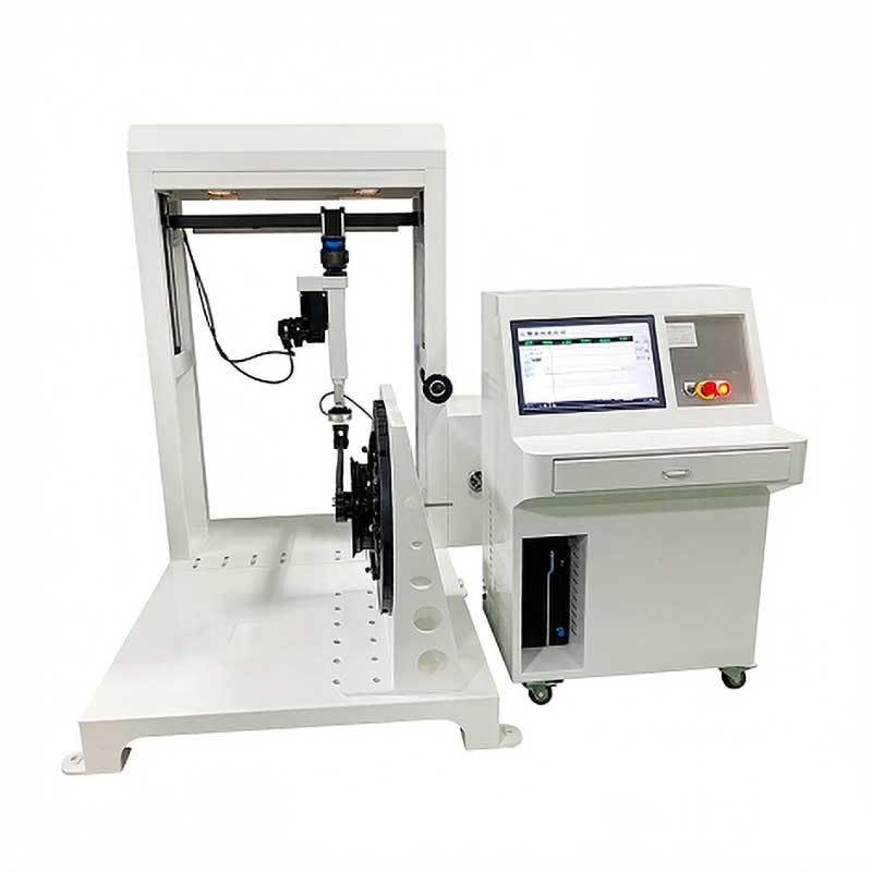
Key equipment specifications for a compliant torsional fatigue testing machine include:
The Motorcycle Wheel Torsional Fatigue Tester from Derui is designed to meet all of these specifications. It features a servo-controlled rotary actuator for precise torque application, a universal rim clamping system that accommodates the full range of motorcycle wheel sizes, and integrated safety interlocks that automatically halt the test upon specimen failure.
Step-by-Step Test Procedure
The following procedure outlines the complete ISO 8644 torsional fatigue test from specimen preparation through post-test evaluation. Each step must be followed precisely to ensure valid, repeatable results that will withstand regulatory scrutiny.
Step 1: Specimen Selection and Documentation
Select a production-representative wheel specimen from a standard manufacturing batch. The specimen must not be specially prepared, hand-finished, or subjected to any post-production treatment beyond what a standard production wheel receives. Before testing begins, document the following information in the test report:
- Wheel model number, part number, and production batch code
- Material specification (e.g., A356-T6 aluminum alloy, carbon fiber layup schedule, steel spoke specification)
- Wheel dimensions: rim diameter, rim width, offset, hub bore diameter
- Manufacturer’s declared maximum wheel load rating
- Intended motorcycle category (Category 1, 2, or 3)
- Visual inspection results — check for casting porosity, surface cracks, spoke tension uniformity
Step 2: Calculate the Applied Torque
The torsional moment (M) applied during the test is calculated according to the formula specified in ISO 8644. The calculation accounts for the maximum vehicle mass (Mv), the wheel dynamic radius (Rd), a load factor (K), and the category multiplier. For a typical Category 2 motorcycle wheel with a maximum vehicle mass of 280 kg and a dynamic radius of 0.31 m, the calculation typically yields an applied moment in the range of 900 to 1,200 Nm.
The standard requires that the calculated moment be rounded up to the nearest convenient value for the test machine setting. It is critical that test engineers document the exact calculated value and the actual applied value, as auditors will check this during type approval reviews.
Step 3: Mount the Wheel on the Test Fixture
The wheel is mounted on the test machine with the rim rigidly clamped and the hub free to rotate. The mounting procedure is critical and must follow these guidelines:
- Clamp the rim at a minimum of four equally spaced points around the circumference, with additional clamps as needed for large-diameter wheels to prevent rim flexing
- Ensure the wheel axis is perfectly aligned with the rotation axis of the test machine (within 0.5 mm runout)
- Apply the clamping force evenly to avoid introducing pre-stress into the wheel structure
- For spoked wheels, verify that all spokes are at their correct tension per the manufacturer’s specification before mounting
Step 4: Apply the Rotating Bending Moment
Start the test machine and gradually increase the applied torque to the calculated test value. The ISO 8644 standard specifies the following test conditions:
Rotation Direction: Continuous unidirectional rotation of the bending moment vector
Rotation Speed: 100 to 600 RPM (manufacturer’s choice within this range)
Minimum Cycles: 500,000 complete rotations of the moment vector
Test Temperature: 23 degrees Celsius plus or minus 5 degrees
Pass Criteria: No visible crack, fracture, or permanent deformation exceeding limits
During the test, the bending moment vector rotates around the wheel axis, which means every spoke and every section of the rim experiences the full stress cycle during each revolution of the moment vector. This is what makes the torsional fatigue test so effective at identifying potential failure points across the entire wheel structure.
Step 5: Monitor and Inspect
Throughout the test, the machine should continuously monitor the applied torque and automatically record the cycle count. Modern testing machines like the Derui Motorcycle Wheel Torsional Fatigue Tester include automatic failure detection that triggers an immediate stop when a sudden drop in torque is detected — this typically indicates that a crack has propagated to the point of structural failure.
Visual inspections should be conducted at regular intervals: at least every 100,000 cycles, or more frequently if the wheel is a new design or uses an unproven material. Inspectors should use a combination of visual examination, dye penetrant testing, and, where available, acoustic emission monitoring to detect crack initiation at the earliest possible stage.
Step 6: Post-Test Evaluation
Upon completion of the 500,000 minimum cycles (or upon premature failure), conduct a thorough post-test inspection. The wheel passes the test only if it meets all of the following criteria:
- No visible cracks or fractures anywhere on the wheel structure (rim, hub, spokes, fasteners)
- No permanent deformation of the rim bead seat that would prevent proper tire seating
- No loosening of spoke nipples, wheel bolts, or other fasteners beyond the initial settling specified by the manufacturer
- No evidence of hub bearing seat distortion that would affect bearing fit
If any of these conditions are not met, the wheel fails the test and the manufacturer must investigate the root cause, implement design or process corrections, and re-test with new specimens.
Test Parameters and Acceptance Criteria
The following table summarizes the critical parameters that must be controlled during the test, along with their permissible tolerances and the impact of non-compliance on test validity:
Common Failure Modes in Torsional Testing
Through years of testing experience and analysis of industry failure data, several distinct failure modes have been identified in motorcycle wheel torsional fatigue testing. Understanding these patterns helps both testing engineers and design engineers identify potential weaknesses early in the development process.
Spoke Fatigue Fracture (Spoked Wheels)
The most common failure mode for spoked wheels is fatigue fracture of individual spokes, typically occurring at the spoke head or at the bend where the spoke enters the hub flange. This accounts for approximately 45% of all torsional fatigue failures in spoked wheel designs. The failure mechanism is classic high-cycle fatigue: micro-cracks initiate at stress concentrations (surface defects, corrosion pits, or tool marks from the spoke manufacturing process) and propagate under cyclic torsional loading until the spoke cross-section is reduced to the point of sudden fracture.
Hub Flange Cracking
Hub flange cracks typically initiate at the root of the spoke holes in cast or forged aluminum hubs. These cracks are driven by stress concentration at the sharp edges of the spoke holes combined with the cyclic bending load applied to the hub during the torsional test. This failure mode represents about 25% of reported failures and is particularly prevalent in hubs that have not been properly stress-relieved after machining.
Rim Spoke Bed Cracking (Cast Alloy Wheels)
For one-piece cast alloy wheels, the transition zone between the rim well and the spoke (or web) section is a known stress concentrator. Cracks initiating in this region account for approximately 20% of cast wheel failures. The root cause is typically related to casting porosity or inadequate fillet radii at the spoke-to-rim junction, which create localized stress peaks during the rotating bending moment applied in the torsional test.
Radial Fatigue Testing: How It Differs
While this article focuses on the torsional fatigue test, it is important to understand how it differs from the radial fatigue test that is also specified in ISO 8644. Both tests must be passed for full type approval, and each targets different failure modes.
In the radial fatigue test, the wheel is rotated under a constant radial force applied through a rotating drum or a fixed load arm. This test simulates the vertical loads that the wheel experiences from the vehicle weight, road roughness, and dynamic effects such as bumps and pothole impacts. The minimum cycle count for the radial test is 1,000,000 cycles — twice the minimum for the torsional test.
The key difference in the loading mechanics is that the radial test applies force through the wheel center (axial direction), while the torsional test applies a rotating bending moment about the wheel axis. As a result, the two tests stress different parts of the wheel structure in different ways. A wheel that passes the radial test may still fail the torsional test, and vice versa. This is why both tests are mandatory under ISO 8644.
Some advanced testing laboratories use combined loading rigs that can apply torsional and radial loads simultaneously, providing a more realistic simulation of actual riding conditions. However, for type approval purposes, the two tests are typically conducted separately as specified by the standard.
Best Practices for Manufacturers
Based on extensive experience working with motorcycle wheel manufacturers worldwide, the following best practices can significantly improve first-pass yield rates in ISO 8644 torsional fatigue testing:
- Optimize spoke geometry for stress distribution — Use finite element analysis (FEA) during the design phase to identify and eliminate stress concentrations at spoke heads, bends, and hub flange transitions. Even small increases in fillet radii (from 0.5 mm to 1.0 mm) can improve fatigue life by 30% or more.
- Control spoke tension uniformity — For spoked wheels, the variation in spoke tension between individual spokes should not exceed plus or minus 5% of the target value. Uneven spoke tension causes some spokes to carry disproportionately higher loads during the torsional test, leading to premature failure of the most highly stressed spokes.
- Implement proper surface finishing — Surface defects such as machining marks, tool chatter, and grinding burns act as fatigue crack initiation sites. Ensure that all critical surfaces (spoke heads, hub flange spoke holes, spoke-to-rim transitions) are finished to Ra 1.6 micrometers or better.
- Use statistical sampling — Test a minimum of 3 specimens per wheel design to establish statistical confidence. For high-volume production lines, consider ongoing sampling at a rate of 1 wheel per 1,000 units produced.
- Maintain equipment calibration — Calibrate the torque measurement system on your testing machine at least annually, or whenever the machine undergoes maintenance or repair. A torque error of just 2% can mean the difference between a pass and a fail on marginal designs.
- Document everything thoroughly — Test reports should include specimen identification, calculated and actual applied moments, cycle counts, all visual inspection records, photographs of any defects found, and a clear pass/fail determination with reference to the specific ISO 8644 acceptance criteria.
Frequently Asked Questions
What is the minimum number of cycles required for the ISO 8644 torsional fatigue test?
The minimum is 500,000 complete rotations of the bending moment vector. The wheel must complete this number of cycles without any visible crack, fracture, or structural failure to pass the test. Some manufacturers test beyond the minimum (up to 1,000,000 cycles) to provide additional safety margin.
Can I use the same wheel specimen for both torsional and radial fatigue tests?
No. ISO 8644 requires separate specimens for each test. A wheel that has been subjected to the torsional fatigue test has already experienced significant cyclic loading that may have initiated sub-surface damage. Using the same specimen for the radial test would produce invalid results because the wheel is no longer in its “as-new” condition.
Does ISO 8644 apply to carbon fiber motorcycle wheels?
Yes. The 2023 revision of ISO 8644 explicitly includes composite wheels within its scope. The test procedure is the same (500,000 cycles of rotating bending moment), but the standard includes additional notes regarding the anisotropic nature of composite materials and the importance of testing in the manufacturer’s specified orientation.
How do I calculate the correct torsional moment for my specific wheel?
The torsional moment is calculated using the formula provided in ISO 8644 Clause 5, which takes into account the maximum vehicle mass, the wheel’s dynamic load radius, a load distribution factor, and the category-specific multiplier. If you are uncertain about the calculation, contact your testing equipment supplier — they can typically provide calculation assistance based on your wheel specifications.
What happens if a wheel fails the test before 500,000 cycles?
The wheel fails the test and cannot be approved for the intended vehicle category. The manufacturer must conduct a failure analysis to determine the root cause, implement corrective actions (design changes, material upgrades, process improvements), and re-test with new specimens. It is common to iterate through 2 to 3 design-test cycles before achieving a reliable pass, particularly for new wheel designs.
Is ISO 8644 recognized by all major motorcycle markets?
ISO 8644 is recognized and referenced by regulatory bodies in the European Union (under the type approval framework), Japan (JIS D 4210 references ISO 8644), and India (AIS standards align with ISO 8644 requirements). China’s GB/T standards for motorcycle wheels are also harmonized with ISO 8644. In markets that do not directly reference ISO 8644, equivalent national standards with similar requirements typically apply.
What rotation speed should I use for the test?
ISO 8644 permits any rotation speed between 100 and 600 RPM. Lower speeds are generally preferred for new or unproven designs because they reduce the risk of heat-related effects and allow more time for visual monitoring. Higher speeds reduce total test time (at 600 RPM, 500,000 cycles take approximately 14 hours) but must not be so high that they cause excessive heating of the wheel or test fixture.
Do I need to test both front and rear wheels separately?
Yes, if the front and rear wheels are different designs (which is typically the case for motorcycles). Each wheel design must be tested independently because the front and rear wheels experience different loading conditions in service (the rear wheel carries a higher proportion of the vehicle mass and transmits driving torque). Each unique wheel part number requires its own set of test specimens and its own test report.
How often should torsional fatigue testing equipment be calibrated?
Best practice is to calibrate the torque measurement system at least once per year, or more frequently if the equipment is used for high-volume production testing. Calibration should be traceable to national or international standards (ISO 17025 accredited calibration laboratory is preferred). Between annual calibrations, verify the system with a reference torque tool at least quarterly.
Conclusion
The ISO 8644 torsional fatigue test is an essential safety verification for every motorcycle wheel that enters the global market. By simulating the severe cornering loads that wheels experience throughout their service life, this test identifies potential structural weaknesses before they become life-threatening failures on the road.
For manufacturers, investing in high-quality testing equipment and following rigorous test procedures is not merely a regulatory checkbox — it is a fundamental responsibility to rider safety and brand reputation. A single wheel recall can cost millions of dollars in direct costs, legal liabilities, and brand damage that takes years to repair.
Whether you are establishing a new motorcycle wheel testing laboratory or upgrading existing equipment, selecting the right torsional fatigue testing machine is one of the most important decisions you will make. The Motorcycle Wheel Torsional Fatigue Tester from Derui provides ISO 8644-compliant testing capability with the precision, reliability, and automation features that modern manufacturing environments demand.
Related Products
Need Professional motorcycle testing Equipment?
Explore our range of testing machines designed for compliance with international standards including ISO 8644.