Derui chamber
📑 Table of Contents
Introduction
Bicycle brake systems are the most critical safety component on any bicycle, responsible for decelerating or stopping the vehicle under varying loads, speeds, and environmental conditions. Brake endurance testing is a fundamental verification procedure mandated by international standards such as ISO 4210-2 and EN 14764/14766, designed to ensure that braking systems maintain consistent performance throughout their service life without catastrophic failure.
This guide provides a complete technical walkthrough of bicycle brake endurance testing procedures, covering equipment requirements, test setup, execution steps, data interpretation, and compliance criteria. Whether you are a quality engineer in a bicycle manufacturing facility, a test laboratory technician, or a product development engineer validating a new brake design, this article will serve as a practical reference for setting up and executing endurance tests that meet international certification requirements.
📌 Key Takeaway: Brake endurance testing is not optional — it is a mandatory safety verification under ISO 4210-2 Clause 4.7 and EN 14764/14766. Failure to demonstrate compliance can result in certification denial and product recall risks.
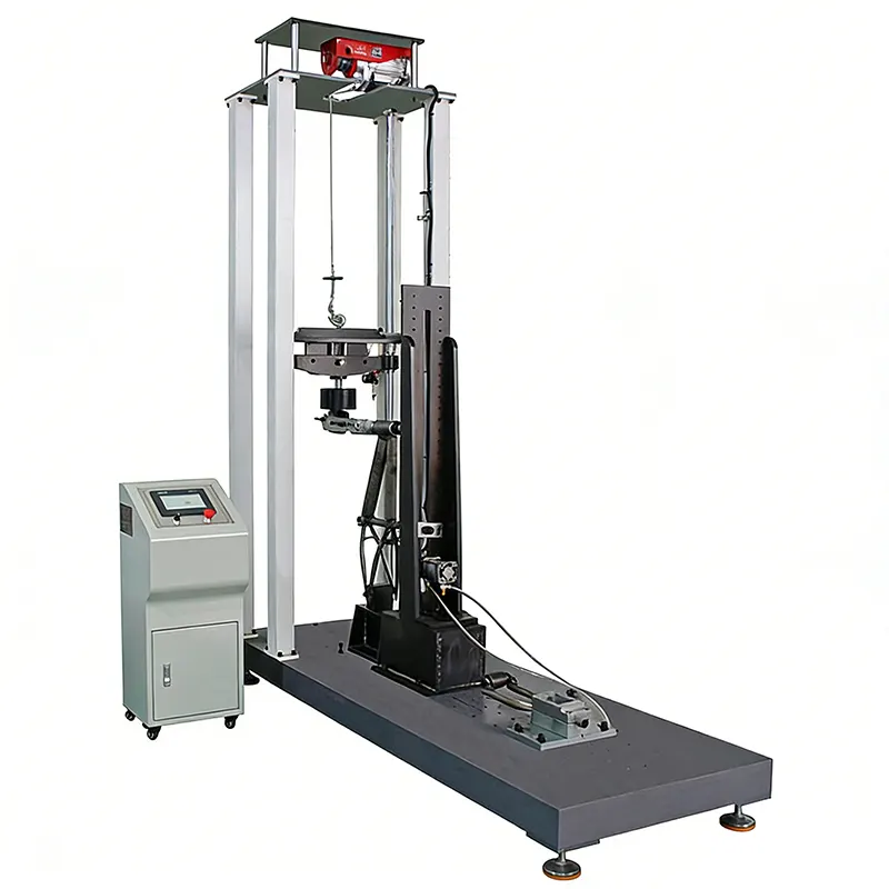 Bicycle Impact And Drop Test Machine – brake endurance testing equipment” style=”border-radius:10px;box-shadow:0 4px 20px rgba(0,0,0,0.1);max-width:100%”>
Why Brake Endurance Testing Matters
Brake endurance testing evaluates the ability of a braking system to withstand repeated braking cycles without loss of performance, structural failure, or excessive wear that could compromise safety. Unlike static strength tests that apply a single peak load, endurance tests simulate real-world usage patterns where brakes are applied hundreds or thousands of times over the lifespan of the bicycle.
The consequences of inadequate brake endurance are well-documented in both laboratory failures and field incidents. Common failure modes include:
- Brake lever pivot pin fatigue fracture due to repeated high-force actuation
- Cable tension loss from housing compression or stranded cable wire fracture
- Brake shoe/disc pad wear exceeding permissible limits before next scheduled maintenance
- Hydraulic brake fluid leakage due to seal degradation under thermal cycling
- Caliper mounting bracket fatigue cracking from asymmetric load distribution
Endurance testing is particularly important for electric bicycles (e-bikes), where higher system weights and assisted speeds place greater thermal and mechanical demands on braking systems. ISO 4210-2 explicitly requires brake endurance verification for all bicycle types, with additional stringency for Class 3 e-bikes capable of speeds up to 45 km/h.
Applicable Standards and Test Requirements
Several international standards govern bicycle brake endurance testing. The specific requirements vary by bicycle type, but the underlying principles are consistent: verify that the brake system can sustain repeated actuation without performance degradation or structural failure.
ISO 4210-2:2025 Clause 4.7 specifies the general brake test procedure: apply the brake progressively to achieve the specified braking force, hold for 5 seconds, release, and repeat for the required number of cycles. The braking force is applied at the tire-road interface using a dynamometer drum or calibrated brake test rig. The standard requires a minimum of 500 cycles for rim brakes and 1000 cycles for disc brakes, reflecting the different wear characteristics and heat dissipation profiles of the two systems.
Test Equipment and Instrumentation
A properly equipped brake endurance test station consists of the following core components:
1. Brake Test Rig
The test rig must securely mount the bicycle frame or fork in a fixed orientation while allowing the wheel to rotate freely against a load drum. The drum shall have a surface roughness and diameter representative of actual road conditions — typically 200 mm to 300 mm diameter with an abrasive surface (Ra ≈ 1.6 μm). The drum is driven by an electric motor with variable speed control (0–60 km/h equivalent).
Key specifications for the brake test rig:
- Maximum test speed: ≥ 60 km/h (for e-bike testing)
- Braking force application: Servo-hydraulic or pneumatic actuator with ≤ 2% force error
- Force measurement: Load cell calibrated to ±0.5% full scale, minimum 2000 N capacity
- Cycle counting: Non-contact proximity sensor or encoder with ±1 cycle accuracy
2. Force Application System
For brake lever-actuated systems, a programmable linear actuator simulates human hand force on the brake lever. The actuator must be capable of applying the specified force (typically 80 N to 200 N depending on brake type and standard) with a repeatability of ±2 N. The actuator stroke and speed should be programmable to simulate different braking styles (gradual application vs. panic stop).
For hub brakes and coaster brakes, the force is applied directly to the brake actuation mechanism using a calibrated linkage system. Torque measurement at the wheel hub is preferred over lever force for these systems, as it directly correlates with braking performance.
3. Data Acquisition System
A multi-channel DAQ system records the following parameters at each brake application:
- Applied brake force (N) — measured at lever or actuator
- Deceleration rate (m/s²) — derived from wheel speed sensor
- Stopping distance (mm) — measured from brake application to wheel stop
- Brake temperature (°C) — infrared sensor or embedded thermocouple on brake rotor/pad
- Actuation force vs. time curve — to detect changes in brake responsiveness
Data should be sampled at a minimum of 100 Hz to capture transient behavior during brake application and release. Real-time monitoring software should flag any cycle where braking force deviates by more than 10% from the target value, or where stopping distance increases by more than 15% compared to the baseline measurement at cycle 1.
Step-by-Step Test Procedure
The following procedure follows ISO 4210-2:2025 Clause 4.7 and is applicable to both rim and disc brake systems. All measurements should be performed at ambient laboratory conditions (23°C ± 5°C, 50% ± 20% RH) unless otherwise specified for thermal testing.
Step 1: Pre-Test Inspection
Before mounting the bicycle on the test rig, perform a complete visual and functional inspection of the brake system:
- Verify brake pad/shoe wear is within manufacturer specifications
- Check cable tension (for cable-actuated brakes) or hydraulic fluid level (for hydraulic brakes)
- Inspect rotor straightness (disc brakes) — runout must not exceed 0.2 mm TIR
- Confirm brake lever pivot moves freely without binding
- Record initial pad thickness and rotor thickness for wear calculation
Step 2: Mounting and Setup
Secure the bicycle frame to the test rig using calibrated torque values for all mounting points. The front fork is tested independently from the rear triangle. For fork-mounted brake tests, the fork is clamped at the steering tube with the wheel axle secured to the test rig’s load drum axle. Ensure the wheel is properly aligned and the tire is inflated to the manufacturer’s recommended pressure (typically 40–80 psi depending on tire size).
Connect the force application actuator to the brake lever using a custom adapter that does not interfere with the lever’s natural pivot arc. Set the actuator force profile to “ramp-hold-release” with a 0.5-second ramp time, 5-second hold, and 1-second release. This profile approximates a deliberate braking action without introducing artificial shock loads.
Step 3: Baseline Measurement
Before starting the endurance cycling, perform 5 baseline brake applications at the target force and record the following:
- Average deceleration (m/s²)
- Average stopping distance (mm)
- Peak brake temperature (°C)
- Actuation force at peak deceleration (N)
These baseline values are used as the reference for evaluating performance degradation throughout the test. A brake system that shows more than 15% degradation in any parameter at the conclusion of the endurance cycles is considered to have failed the endurance requirement.
Step 4: Endurance Cycling
Start the endurance test program. The test rig should automatically execute the following sequence for each cycle:
- Accelerate the drum to the target test speed (25 km/h for rim brake, 35 km/h for disc brake)
- Apply the brake actuator to achieve the target force (120 N or 150 N)
- Hold the force until wheel speed drops to ≤ 5 km/h (or a maximum of 5 seconds, whichever comes first)
- Release the brake and allow the wheel to re-accelerate to test speed
- Record all DAQ channels for the cycle
- Repeat for the total specified cycle count
For disc brake systems on e-bikes, insert a thermal soak phase every 100 cycles: after the 100th cycle, allow the brake to cool to ≤ 50°C before resuming testing. This prevents unrealistic thermal accumulation that does not occur in actual riding, where airflow during non-braking intervals provides continuous cooling.
Step 5: Intermediate Checks
At 25%, 50%, and 75% of the total cycle count, pause the test and perform a partial inspection:
- Measure pad/shoe thickness and compare to baseline
- Check for visible cracking on brake levers, calipers, or mounting brackets
- Verify hydraulic connections are leak-free (hydraulic brakes only)
- Record deceleration and stopping distance for the current cycle set
Step 6: Final Evaluation
Upon completion of all endurance cycles, perform a final full evaluation:
- Conduct 5 post-test brake applications and compare to baseline data
- Measure total pad wear — must not exceed 50% of initial pad thickness
- Perform a static pull test at 200% of the endurance actuation force — no structural failure allowed
- Document all observed defects with photographs
The brake system passes the endurance test if: (a) no structural failure occurred, (b) braking force degradation is ≤ 15%, (c) pad wear is within limits, and (d) all functions are intact without leakage or binding.
🔬 Technical Note: For hydraulic disc brakes, the endurance test must include at least 10 full-pressure hold cycles (actuation force held for 30 seconds) to verify seal integrity under sustained pressure. This is not explicitly required by ISO 4210 but is considered best practice by leading brake manufacturers.
Common Failure Modes and Diagnosis
Understanding how brake systems fail during endurance testing helps engineers design more robust components and identify root causes when test articles fail. The following are the most frequently observed failure modes in laboratory brake endurance tests.
1. Pad Material Fade
Brake pad material fade occurs when the frictional characteristics of the pad change due to sustained high temperature. Organic pad compounds are particularly susceptible to fade above 300°C, where the phenolic resin binder begins to decompose. Symptoms include a gradual increase in actuation force required to achieve the same deceleration, and a “mushy” or inconsistent feel during the hold phase.
Diagnosis: Monitor brake temperature continuously. If pad temperature exceeds the manufacturer-specified maximum operating temperature for more than 10 consecutive cycles, the test should be paused for cooling. Consider using sintered metal pads for high-performance applications where endurance testing generates sustained high temperatures.
2. Cable Stretch and Housing Compression
Cable-actuated brake systems rely on precise tension to transmit actuation force from the lever to the caliper. During endurance testing, the stranded steel cable undergoes progressive elongation (stretch) while the housing compresses at the end caps. The combined effect is a loss of actuation efficiency — more lever travel is required to achieve the same caliper piston movement.
Diagnosis: Measure actuation force at the lever and compare it to the force measured at the caliper piston (using a secondary load cell). A growing discrepancy between the two indicates cable system losses. The remedy is to use compressionless brake housing and pre-stretched cables, or to switch to a hydraulic actuation system.
3. Caliper Mounting Fatigue
Disc brake calipers are mounted to the fork or frame using two or four bolts that experience asymmetric loading during braking. The reaction torque from the caliper body creates a bending moment on the mounting bolts, which can lead to fatigue cracking after several thousand cycles. This failure mode is especially prevalent in lightweight aluminum calipers mounted to carbon fiber forks.
Diagnosis: Use dye penetrant inspection (DPI) or magnetic particle inspection (MPI) on all caliper mounting brackets after the endurance test. Replace any bracket showing crack indications. Increase mounting bolt diameter or use higher-grade fasteners (e.g., 12.9 grade socket head cap screws) if fatigue life is insufficient.
4. Lever Pivot Wear
The brake lever pivot bushing or bearing experiences repeated oscillating loads during endurance testing. Over time, the pivot clearance increases due to abrasive wear, resulting in lever wobble and inconsistent actuation feel. In extreme cases, the pivot pin itself can fracture if made from low-toughness material.
Diagnosis: Measure lever pivot play before and after the endurance test. Play exceeding 0.5 mm is considered excessive. Use needle roller bearings instead of plain bushings for high-cycle applications, and ensure the pivot pin is manufactured from heat-treated alloy steel (e.g., 4140 or 4340).
Test Report and Documentation
A complete brake endurance test report should include the following sections to satisfy certification body requirements and provide a traceable record of the verification process.
- Test Object Description: Bicycle model, frame number, brake system make/model, serial numbers of all brake components
- Test Standard and Clauses: Explicitly state which standard and clause was followed (e.g., ISO 4210-2:2025, Clause 4.7)
- Test Equipment Calibration: List all equipment used with calibration dates and traceability certificates
- Test Parameters: Target force, cycle count, test speed, ambient conditions
- Raw Data Annex: Deceleration vs. cycle number plot, temperature vs. cycle number plot, actuation force vs. cycle number plot
- Photographic Evidence: Pre-test, intermediate, and post-test photographs showing pad wear, any damage, and setup details
- Pass/Fail Decision: Explicit statement of compliance with each requirement, with quantitative evidence
The test report must be signed by the test engineer and reviewed by a qualified technical manager. For certification submissions, the report should be formatted according to the certification body’s template (e.g., TÜV, SGS, Intertek) and include a statement of conformity with the applicable standard.
Frequently Asked Questions
Q1: How many brake endurance test samples are required for certification?
A1: Most certification schemes require 2–3 samples for brake endurance testing. ISO 4210-2 does not explicitly specify sample size, but certification bodies typically require n=2 for type approval and n=5 for production verification. Check with your specific certifier for their requirements.
Q2: Can I combine brake endurance testing with the brake performance test in a single test run?
A2: No. ISO 4210-2 defines separate test procedures for brake performance (Clause 4.7.1) and brake endurance (Clause 4.7.2). The performance test measures stopping distance at a single point; the endurance test measures performance retention over many cycles. They must be conducted as distinct test sequences, though they can be performed on the same sample sequentially.
Q3: What is the acceptable deceleration degradation over 500 cycles?
A3: ISO 4210-2 does not specify a numeric degradation limit, but industry practice and most certification body internal procedures treat ≥ 15% degradation in stopping distance or required actuation force as a failure. The rationale is that a 15% degradation represents a perceptible and unsafe reduction in braking performance for the end user.
Q4: Do e-bikes require different brake endurance test parameters?
A4: Yes. E-bikes (particularly Class 2 and Class 3) have higher system weights and can reach higher speeds, both of which increase braking energy. ISO 4210-10 and EN 15194 require brake endurance testing at a simulated speed of 45 km/h for Class 3 e-bikes, compared to 25 km/h for conventional bicycles. The higher speed generates more kinetic energy per brake application, accelerating pad wear and increasing brake temperature.
Q5: How do I simulate real-world brake cooling in the laboratory?
A5: The simplest method is to insert a dwell time between brake applications equal to the time the bicycle would spend accelerating and cruising between braking events in actual use — typically 30–60 seconds. More sophisticated test rigs use forced air cooling directed at the brake rotor to simulate airflow during riding. The goal is to prevent unrealistic thermal accumulation that would not occur in field use.
Q6: What brake pad wear measurement method is most accurate?
A6: The most accurate method is to measure pad thickness using a digital micrometer at three points across the pad width, before and after the test. Repeatability is improved by marking the measurement locations with a fine-tip permanent marker. For disc brake pads, also measure the rotor thickness at the friction path before and after, as excessive rotor wear indicates an incompatible pad material.
Q7: Is it necessary to test both front and rear brakes?
A7: Yes. ISO 4210-2 requires independent testing of front and rear brake systems. The front brake is typically subjected to higher loads (since weight transfer during braking shifts load to the front wheel), while the rear brake experiences different thermal profiles due to lower ventilation. Both must be verified independently.
Q8: Can I use a servo-hydraulic test machine instead of a dedicated brake test rig?
A8: Yes, provided the servo-hydraulic machine can accurately control actuation force, measure deceleration, and count cycles. Many laboratories use multi-axis servo-hydraulic test frames originally designed for component fatigue testing, retrofitted with a brake-specific fixturing package. The key requirement is that the force application and measurement accuracy meet the standard’s tolerances (±5 N for actuation force).
Related Products
Need Professional Bicycle Testing Equipment?
Explore our range of testing machines designed for compliance with international standards.