Derui chamber
Setting up an Deruitester.com/bicycle-impact-and-drop-testing-protecting-frames-from-real-world-damage/”>impact testing machine for bicycle frames is one of the most precision-critical tasks in a testing laboratory. A misconfigured drop tower or incorrectly mounted frame can produce misleading results, causing manufacturers to either over-engineer their products or, worse, release frames that fail in real-world use. This guide walks through every aspect of impact testing machine setup—from selecting the right equipment and configuring test parameters to calibrating sensors and interpreting the resulting data. Whether you are establishing a new bicycle testing lab or upgrading your existing impact testing capabilities, this article provides the technical depth you need to get it right the first time.
🔑 Key Takeaways
- Proper impact testing machine setup is critical for accurate bicycle frame fatigue and crash safety evaluation.
- Key setup parameters include drop height, impact mass, fixture alignment, and data acquisition sampling rate.
- Standard compliance (ISO 4210, EN 14766) dictates specific impact energy levels and test procedures for different frame types.
- Regular calibration of load cells, accelerometers, and drop mechanisms ensures repeatable and defensible test results.
- Common setup mistakes—misaligned anvils, incorrect mass selection, and insufficient data capture—lead to invalid test outcomes.
📑 Table of Contents
- ▸ Why Impact Testing Matters for Bicycle Frames
- ▸ Choosing the Right Impact Testing Machine
- ▸ Site Preparation and Installation
- ▸ Frame Mounting and Fixturing
- ▸ Drop Weight and Height Configuration
- ▸ Sensor Calibration and Data Acquisition
- ▸ Test Parameters by Standard
- ▸ Running the Test: Step-by-Step
- ▸ Interpreting Test Results
- ▸ Common Setup Mistakes and How to Avoid Them
- ▸ Maintenance and Recalibration
- ▸ Frequently Asked Questions
Why Impact Testing Matters for Bicycle Frames
Bicycle frames are subjected to repeated impact loads throughout their service life—potholes, curb drops, rock strikes, and accidental crashes all transmit sudden, high-magnitude forces through the frame tubing. Unlike fatigue loads that accumulate over millions of cycles, impact loads can cause catastrophic failure in a single event. A frame that passes fatigue testing can still shatter on its first encounter with a severe impact if the material has insufficient fracture toughness or if the weld geometry creates a stress concentration point.
International standards such as ISO 4210-6 and EN 14766 mandate specific impact test protocols that simulate these real-world events under controlled laboratory conditions. The test involves dropping a known mass from a specified height onto a designated area of the frame and measuring the frame’s response—typically through residual deformation, visible cracking, or complete structural failure. The data from these tests helps engineers identify weak points in the frame design, validate material selection, and demonstrate regulatory compliance for market access in the EU, US, and Asian markets.
For testing laboratories, the accuracy of impact testing depends almost entirely on how well the testing machine is set up. A drop tower that is not perfectly vertical, a striker with the wrong geometry, or a frame fixture that allows unintended movement can all produce test results that deviate significantly from the true material response. This is why machine setup is not just a one-time installation task but an ongoing discipline that must be revisited before every test series.
Choosing the Right Impact Testing Machine
Not all impact testing machines are suitable for bicycle frame testing. The machine must meet specific requirements in terms of drop height range, striker geometry, fixture compatibility, and data acquisition speed. When selecting a machine, consider the following key specifications:
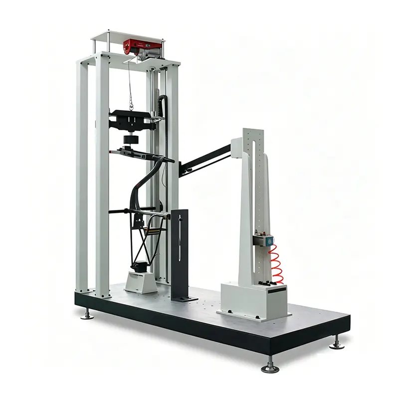
The Bicycle Multi-functional Impact and Drop Test Machine shown above is a popular choice among bicycle manufacturers because it covers the full range of ISO 4210-6 and EN 14766 test requirements. It features a motorized lift mechanism for precise height control, interchangeable strikers for different test points (frame top tube, down tube, fork crown), and a high-speed data acquisition system that captures the full impact force-time curve at 200 kHz. The machine also includes a safety enclosure that prevents operator injury in case of frame fragmentation during testing.
Site Preparation and Installation
Before the machine arrives, the laboratory space must be properly prepared. Impact testing generates significant dynamic loads that can transmit vibrations through the floor, affecting both the test results and neighboring equipment. The following site preparation checklist should be completed before installation:
- Floor load capacity: The machine foundation must support a static load of at least 500 kg and a dynamic load of up to 3000 N during impact events. A reinforced concrete slab of minimum 200 mm thickness is recommended. If the lab is on an elevated floor, a structural engineer should verify the dynamic load capacity.
- Vibration isolation: Install the machine on an anti-vibration pad (minimum 25 mm thick, durometer 60–70 Shore A) or on a dedicated inertia block separated from the surrounding floor by a 20 mm expansion gap. This prevents impact vibrations from propagating to adjacent test equipment.
- Leveling: The machine base must be leveled to within 0.1 mm/m in both longitudinal and transverse directions using a precision machinist’s level. Out-of-level conditions cause the drop mass to deviate from vertical, introducing lateral force components that corrupt the test data.
- Power supply: Dedicated 220V/20A circuit with earth ground resistance < 4 ohms. Voltage fluctuations during motorized lift operation should not exceed ±5%. Install an isolation transformer if the lab shares power with heavy machinery.
- Environmental conditions: Maintain lab temperature at 23 ± 5°C and relative humidity at 50 ± 20%. Temperature fluctuations affect both the frame material properties and the load cell calibration. Avoid placing the machine near HVAC ducts or exterior windows.
- Clearance: Provide at least 1.5 m of clearance on all four sides of the machine for frame loading, striker changes, and maintenance access. Ceiling height must accommodate the fully raised drop mass plus 300 mm of headroom.
- Safety infrastructure: Install a physical guard or safety curtain around the machine perimeter. The control panel should be positioned at least 1.5 m from the drop zone, and an emergency stop button must be accessible from the operator position.
Once the site is prepared, the machine should be anchored to the floor using M16 chemical anchors (minimum 150 mm embedment depth) at all four mounting points. After anchoring, re-verify the level and adjust the leveling feet as needed. Connect the power supply, compressed air (if required for pneumatic clamping), and data acquisition cables before powering on the system.
Frame Mounting and Fixturing
Proper frame mounting is arguably the most critical setup variable in impact testing. The fixture must hold the frame rigidly in the orientation specified by the test standard while ensuring that the impact force is applied precisely to the designated target area. Any movement of the frame within the fixture absorbs energy that should have gone into the frame structure, producing artificially low force readings.
ISO 4210-6 Frame Mounting Requirements
ISO 4210-6 specifies impact tests at two locations on the bicycle frame: the top tube and the down tube. For each location, the frame must be mounted with the head tube and seat tube clamped at specific angles. The standard requires:
- Frame positioned with the bottom bracket shell facing downward, clamped at the head tube and seat tube junctions
- Striker centered on the test point with a positioning tolerance of ±2 mm in both longitudinal and lateral directions
- Clamping force sufficient to prevent frame movement—typically 500–800 N per clamp, verified using torque wrenches on the clamp bolts
- Fork removed (or replaced with a rigid dummy fork) to isolate the frame test from fork compliance
Fixture Design Considerations
The fixture should use V-block or conformal jaw inserts machined from aluminum or nylon to distribute clamping forces without crushing the frame tubing. Steel jaws can damage thin-walled carbon fiber frames and should be avoided. For carbon frames specifically, the clamp contact area should be at least 1000 mm² per clamp to keep the contact pressure below 5 MPa, preventing local fiber damage that could act as an artificial crack initiation site.
The fixture must also allow rapid reorientation of the frame between top tube and down tube tests. A well-designed fixture uses a quick-release pivot mechanism that rotates the frame 180° without unclamping, reducing setup time from 15 minutes to under 3 minutes per test point. This is particularly important in high-throughput production testing environments where 20–30 frames may be tested per day.
Drop Weight and Height Configuration
The impact energy delivered to the frame is determined by the drop mass and drop height according to the equation E = mgh, where E is impact energy (J), m is drop mass (kg), g is gravitational acceleration (9.81 m/s²), and h is drop height (m). ISO 4210-6 specifies a total impact energy of 35 J for the top tube test and 35 J for the down tube test, applied using a 22.5 kg drop mass. EN 14766 (mountain bicycle frames) specifies a higher energy of 40 J due to the more demanding use case.
When configuring the drop weight, verify the actual mass using a calibrated scale (accuracy ±0.01 kg) rather than relying on the manufacturer’s stamped value. The drop height should be measured from the striker surface to the frame test point using the machine’s built-in height gauge, and cross-checked with a steel ruler. Even a 2 mm error in drop height translates to approximately 0.44 J of energy deviation at the 22.5 kg mass level, which can be the difference between a pass and fail result for borderline frames.
The striker geometry also matters. ISO 4210-6 specifies a flat striker with a 25 mm diameter contact face and 5 mm edge radius. For carbon fiber frames, some labs use a hemispherical striker (R = 50 mm) to distribute the force over a larger area, but this deviates from the standard and should only be used for research purposes. Always document the striker geometry used in the test report.
Sensor Calibration and Data Acquisition
The load cell is the heart of the impact testing system—it converts the mechanical impact force into an electrical signal that the data acquisition system records. A typical bicycle impact test generates a force pulse that lasts only 2–10 milliseconds, which means the load cell and data acquisition system must have sufficient bandwidth to capture the entire event without distortion.
Load Cell Specifications
- Type: Piezoelectric (recommended for impact testing due to high natural frequency > 50 kHz) or strain gauge (acceptable if natural frequency > 10 kHz)
- Range: 0–20 kN (bicycle frame impacts typically peak at 3–8 kN, so a 20 kN cell provides 2.5× headroom)
- Accuracy: ±0.5% of reading or ±0.1% of full scale, whichever is greater
- Calibration interval: Every 12 months, or after any suspected overload event, using a reference force standard traceable to a national metrology institute
Data Acquisition System Setup
The data acquisition (DAQ) system must be configured to sample at a rate that captures the full force-time curve without aliasing. According to the Nyquist theorem, the sampling rate must be at least twice the highest frequency component of interest. For bicycle frame impacts, significant frequency content extends to approximately 5 kHz, so a minimum sampling rate of 10 kHz is required. However, most modern systems operate at 100–200 kHz to provide detailed pulse shape information.
Configure the DAQ with the following settings before each test series:
- Sampling rate: 100 kHz minimum
- Pre-trigger buffer: 5 ms (captures the baseline force before impact)
- Post-trigger buffer: 50 ms (captures the full rebound and any secondary impacts)
- Trigger level: 200 N (well above noise floor but below expected peak force)
- Anti-aliasing filter: Low-pass at 0.4 × sampling rate (e.g., 40 kHz cutoff at 100 kHz sampling)
- Signal conditioning: IEPE (Integrated Electronics Piezo Electric) excitation at 4 mA if using piezoelectric load cell
Before running the first test of the day, perform a quick zero-check by recording 5 seconds of data with no load applied. The baseline should be stable within ±5 N. If drift exceeds this threshold, allow the load cell to warm up for 30 minutes and recheck. Persistent drift indicates either a faulty load cell cable or a damaged charge amplifier.
Test Parameters by Standard
Different standards apply to different bicycle categories. Using the wrong standard for your frame type will produce irrelevant results and may lead to non-compliant products reaching the market. The table below summarizes the key parameters for the three most commonly applied bicycle frame impact standards:
Note that EN 14766 has been officially replaced by ISO 4210-6 for new certifications, but many manufacturers still test to both standards for legacy compliance. If your frame is classified as an MTB, apply the 40 J energy level even if you are also testing to ISO 4210-6, as the more demanding standard takes precedence for that product category.
Running the Test: Step-by-Step
Once the machine is set up, calibrated, and the frame is properly mounted, follow this step-by-step procedure to execute the impact test:
- Pre-test inspection: Visually inspect the frame for any pre-existing damage. Document the frame serial number, material, and geometry. Photograph the test area before impact for post-test comparison.
- Verify frame position: Use a height gauge to confirm the striker will contact the center of the test point within ±2 mm tolerance. Mark the target with a removable marker for visual verification.
- Zero the load cell: With the drop mass resting on the safety stop (not on the frame), zero the load cell and verify baseline stability for 10 seconds.
- Set drop height: Enter the calculated drop height into the machine controller. The controller will automatically raise the drop mass to the specified height. Verify the height using the built-in encoder readout.
- Arm the DAQ: Start the data acquisition system in armed mode. The system will begin recording when the trigger level (200 N) is reached.
- Clear the area: Ensure all personnel are behind the safety barrier. Verify the safety interlock is engaged.
- Release the drop mass: Press the drop button on the controller. The electromagnet releases the drop mass, which falls freely onto the frame test point.
- Capture the data: The DAQ records the full force-time curve from pre-trigger through post-trigger buffer. Verify that the peak force, pulse duration, and total impulse are captured.
- Post-test inspection: Carefully remove the frame from the fixture. Inspect the impact area for visible cracks, delamination (for carbon frames), or permanent deformation. Measure residual deformation using a straight edge and feeler gauge.
- Save and export data: Save the force-time curve, peak force, impulse, and test metadata (frame ID, standard, parameters) to the laboratory database. Export a PDF test report for the quality file.
For production testing, steps 1–10 take approximately 8–12 minutes per frame per test point. With a well-organized workflow, a single technician can complete 4–6 full frame tests (both top tube and down tube) per hour.
Interpreting Test Results
The force-time curve from an impact test contains rich information about the frame’s structural behavior. Understanding how to read this curve is essential for making informed engineering decisions:
- Peak force: The maximum force recorded during the impact. A higher peak force indicates greater frame stiffness at the test point. Typical bicycle frame impacts produce peak forces of 3–8 kN. Forces above 10 kN suggest the frame is extremely stiff, which may transmit excessive vibration to the rider.
- Pulse duration: The time from initial contact to the point where force returns to zero. Longer pulse durations (8–10 ms) indicate the frame is absorbing energy through controlled deformation, which is desirable. Short durations (2–4 ms) suggest brittle behavior with minimal energy absorption.
- Impulse: The area under the force-time curve, representing the total momentum transferred during impact. Compare the measured impulse to the theoretical impulse (drop mass × impact velocity) to verify test consistency. Deviations greater than 5% indicate setup problems.
- Residual deformation: The permanent deflection of the frame at the test point after impact. ISO 4210-6 limits this to 5 mm. Carbon frames typically show < 1 mm residual deformation, while aluminum frames may show 2–4 mm due to their ductile behavior.
- Failure mode: If the frame fails, document whether the failure is brittle (clean fracture with no deformation), ductile (significant deformation before fracture), or delamination (separation of composite layers). Brittle failures in aluminum frames indicate potential heat treatment problems; delamination in carbon frames points to manufacturing defects.
Pro Tip: Always compare impact test results against a reference frame of known good quality. Testing a reference frame at the start of each test series validates that the machine is performing consistently and that the setup has not drifted. Keep a log of reference frame results to track long-term machine performance trends.
Common Setup Mistakes and How to Avoid Them
Even experienced technicians can make setup errors that compromise test results. Based on industry experience and audit findings from accredited laboratories, here are the most common mistakes and their prevention:
- Insufficient clamping force: Frames that shift during impact produce artificially low peak forces and long pulse durations. Always verify clamping force with a torque wrench and check for frame movement after each test. If movement is detected, increase clamping force or improve fixture contact geometry.
- Worn striker edges: The striker edge radius wears down over hundreds of tests, changing the contact geometry and concentrating stress at the edge. Inspect the striker before each test series and replace it when edge radius deviates by more than 0.5 mm from specification.
- Dropped frame temperature: Frames brought in from cold storage (e.g., winter shipments) may be below the 23 ± 5°C requirement. Cold aluminum is more brittle and carbon fiber resin systems are stiffer at low temperatures, both of which can cause false failures. Allow frames to acclimate for at least 2 hours before testing.
- Incorrect drop height calculation: The drop height must be measured from the striker face to the frame surface, not from the striker face to the fixture. A 5 mm error in measuring the frame surface position changes the impact energy by approximately 1.1 J, which is significant for borderline frames.
- Overlooking secondary impacts: After the initial impact, the drop mass may rebound and strike the frame again. Some DAQ systems only capture the first impact. Ensure your post-trigger buffer is long enough (≥50 ms) to capture secondary impacts, as they can cause additional damage that affects the pass/fail determination.
- Neglecting cable management: Load cell cables that are tensioned or pinched during the drop introduce electrical noise and can cause trigger errors. Route all cables with sufficient slack and secure them with cable ties away from the drop path.
Maintenance and Recalibration
A well-maintained impact testing machine will provide reliable results for 15–20 years. The following maintenance schedule is recommended for bicycle frame impact testing equipment:
- Daily (before first test): Visual inspection of striker, guide rails, and safety enclosure. Zero-check the load cell. Verify drop height using a reference gauge block.
- Weekly: Clean guide rails and apply light machine oil. Inspect clamp jaw inserts for wear or damage. Check all electrical connections for tightness. Run a reference frame test and compare results to historical data.
- Monthly: Lubricate the lift mechanism (chain or ball screw). Check the electromagnet release mechanism for consistent performance—measured drop velocity should be within ±1% of theoretical (v = √(2gh)). Inspect the load cell cable for signs of wear.
- Annually: Full load cell recalibration by an accredited calibration laboratory. Machine leveling re-verification. DAQ system calibration verification using a known reference signal. Safety interlock functional test. Full documentation review and test report audit.
Keep a maintenance logbook with dates, actions, and technician signatures. Accredited testing laboratories (ISO/IEC 17025) must demonstrate a controlled maintenance program as part of their quality management system. A gap in maintenance records can result in test results being invalidated during laboratory audits.
Frequently Asked Questions
1. What is the maximum drop height I need for bicycle frame impact testing?
For ISO 4210-6 and CPSC 1512, the maximum drop height is approximately 159 mm (with a 22.5 kg mass for 35 J energy). For EN 14766 (mountain bikes), it is approximately 181 mm (for 40 J). A machine with a 1000 mm drop height range provides ample headroom and allows you to perform higher-energy research tests if needed in the future.
2. Can I use the same impact testing machine for bicycle forks?
Yes, with the appropriate fork fixture. Bicycle fork impact testing (ISO 4210-6, Section 6.2) uses the same 22.5 kg drop mass and 35 J energy level, but the fork must be mounted in a dedicated fork fixture that clamps the steerer tube and supports the dropout area. Many machine manufacturers offer interchangeable fork fixtures as accessories.
3. How often should I recalibrate the load cell?
Load cells should be recalibrated every 12 months by an accredited calibration laboratory. However, if the load cell experiences an overload event (force exceeding 120% of rated capacity), it should be recalibrated immediately. Some labs perform a quick verification check monthly using a reference weight or proving ring to detect calibration drift between full recalibrations.
4. What causes a double-peak in the force-time curve?
A double-peak typically indicates that the frame buckled or cracked during the first force peak, causing a sudden loss of stiffness followed by a secondary contact as the drop mass pushes through the damaged area. This is a clear sign of frame failure and should be documented with photographs of the fracture surface. In some cases, a double-peak can also be caused by frame movement within the fixture—verify clamping force if the frame shows no visible damage.
5. Should I test carbon fiber frames differently from aluminum frames?
The test parameters (mass, height, energy) are identical regardless of frame material. However, carbon fiber frames require softer clamp jaw inserts (nylon or aluminum with rubber backing) to prevent local fiber damage. Carbon frames also tend to fail more suddenly (brittle failure mode) compared to aluminum frames, so ensure the safety enclosure is fully closed before releasing the drop mass.
6. What is the acceptable residual deformation after impact?
ISO 4210-6 specifies that residual deformation must not exceed 5 mm at the test point. In practice, well-designed carbon fiber frames show less than 1 mm residual deformation, while aluminum frames typically show 2–4 mm. Steel frames may show 1–3 mm. Any visible crack, regardless of deformation, constitutes a test failure.
7. Can I perform impact testing at non-standard temperatures?
Yes, for research and development purposes. However, results from non-standard temperature tests cannot be used for compliance certification. If you test at extreme temperatures (-20°C or +50°C), be aware that both the frame material properties and the load cell calibration shift. Use a temperature-compensated load cell and document the test temperature in the report.
8. How long does a complete impact test cycle take?
For an experienced technician, the complete cycle—including frame mounting, height setting, DAQ arming, drop, post-test inspection, and data export—takes approximately 8–12 minutes per test point. A full frame test (top tube + down tube) takes 20–25 minutes including repositioning the frame between tests. With a quick-release fixture, this can be reduced to 15 minutes per frame.
Related Products
Need Professional Bicycle Testing Equipment?
Explore our range of testing machines designed for compliance with international standards.