Derui chamber
Table of Contents
- Introduction to ISO 4210 Saddle Fatigue Testing
- Why Saddle Fatigue Testing Matters
- ISO 4210 Standard Overview
- Required Testing Equipment
- Step-by-Step Test Procedure
- Critical Test Parameters
- Common Failure Modes
- Best Practices for Manufacturers
- Frequently Asked Questions
- Conclusion
Introduction to ISO 4210 Bicycle Saddle Fatigue Testing
The bicycle saddle is one of the most critical rider contact points, directly supporting body weight and absorbing road vibrations over thousands of kilometers. A saddle failure during riding can result in serious injury, which is why ISO 4210 mandates rigorous fatigue testing for all bicycle saddles sold in international markets.
Key Takeaways
- ISO 4210 and EN 14766 standards define mandatory test procedures, impact energy levels, and fatigue cycle requirements for bicycle frames and components.
- Accurate fixture alignment and load cell calibration are critical — misalignments of just 2-3 mm can introduce 15-20% measurement errors in fatigue testing results.
- Each component (frame, fork, saddle, brake) has distinct test parameters: frame fatigue requires 50,000-100,000 cycles while brake testing demands higher force thresholds.
- Data acquisition sampling rates of 10 kHz or higher are necessary to capture transient impact events without losing peak force data.
- Regular equipment calibration (every 6-12 months) and documented calibration certificates are essential for ISO-accredited lab compliance.
This guide provides a comprehensive, step-by-step walkthrough of the ISO 4210 bicycle saddle fatigue test procedure, covering the standard requirements, testing equipment, methodology, and best practices that every bicycle manufacturer and testing lab needs to understand.
Why Saddle Fatigue Testing Matters
Bicycle saddles endure cyclic loading throughout their service life. Every pedal stroke, every bump in the road, and every rider position change applies stress to the saddle rails, shell, and cover. Over time, this repeated loading can cause:
- Rail fatigue fractures — cracked or broken saddle rails that cause sudden collapse
- Shell delamination — separation of composite layers in the saddle base
- Cover tearing — material failure at high-stress points
- Clamp interface wear — deformation at the rail-clamp contact zone
According to industry data, saddle-related failures account for approximately 12% of all bicycle component recalls in the European market. Proper fatigue testing before market launch is not just a regulatory requirement — it is a critical safety measure.
ISO 4210 Standard Overview
ISO 4210 is the international standard for bicycle safety requirements, and its fatigue testing provisions are specifically designed to simulate years of real-world riding stress in a controlled laboratory environment.
Key Sections Relevant to Saddle Testing
The standard specifies two primary saddle tests:
- Static strength test — applies a single, high-magnitude load to verify structural integrity under worst-case conditions
- Fatigue test — applies repeated cyclic loading to simulate long-term use and identify potential failure modes
Required Testing Equipment
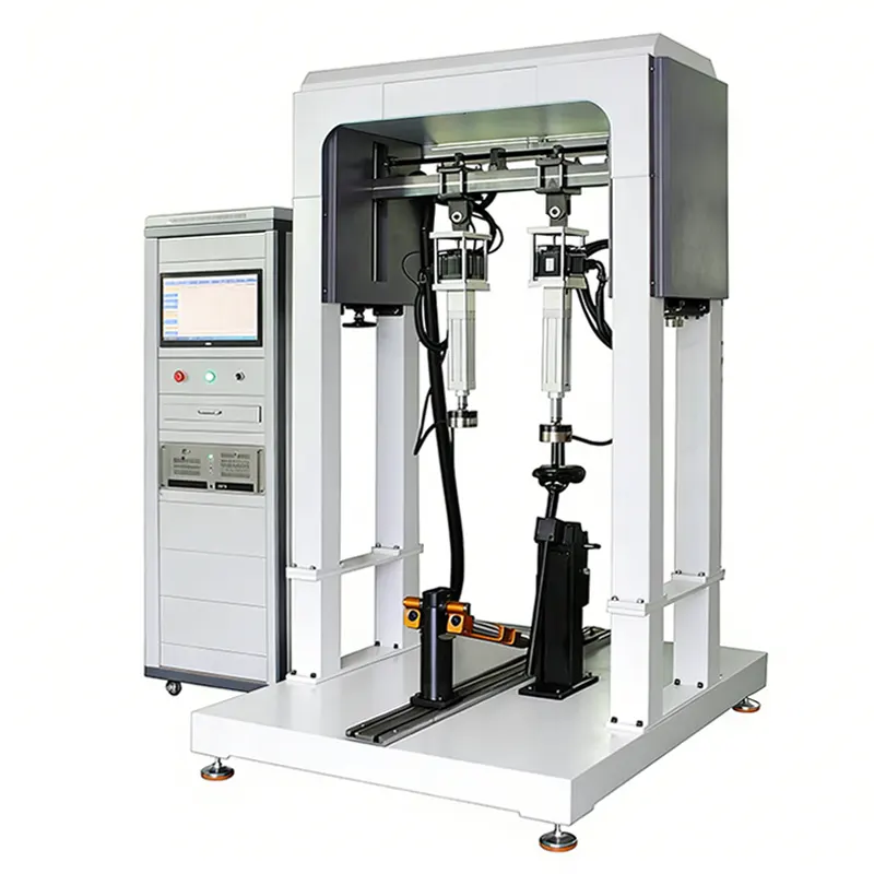
Conducting the ISO 4210 saddle fatigue test requires specialized equipment designed to apply precise, repeatable cyclic loads. The Bicycle Saddle Fatigue Testing Machine is purpose-built for this application.
Equipment Specifications
The Bicycle Saddle Fatigue Testing Machine from Derui meets all these specifications and provides automated cycle counting, real-time monitoring, and compliance reporting.
Step-by-Step Test Procedure
Step 1: Specimen Preparation
Select a production-representative saddle sample. The specimen must be identical to the product that will be sold to consumers — no modifications, reinforcements, or special treatments are permitted.
Before testing:
- Visually inspect the saddle for manufacturing defects
- Record the model, material, rail type (CrMo, titanium, carbon, alloy), and manufacturing batch
- Measure and document rail diameter and saddle dimensions
- Condition the specimen at 23 degrees Celsius plus or minus 5 degrees for at least 4 hours
Step 2: Mount the Saddle
Install the saddle on the test fixture using a standard seat post clamp. The clamp position must match the manufacturer recommended installation configuration:
- Center the rails in the clamp at the midpoint of the saddle
- Tighten the clamp to the manufacturer specified torque
- Verify that the saddle is level (0 degrees tilt) unless the manufacturer specifies otherwise
Step 3: Apply the Test Load
Position the loading mechanism at the saddle nose region, which is the most critical failure zone. The ISO 4210 standard specifies:
Cyclic force: 1,200 N (minimum)
Loading direction: Vertical (downward)
Application point: 25 mm from saddle nose tip
Number of cycles: 100,000 cycles (minimum)
Load frequency: 1 to 4 Hz
Step 4: Run the Fatigue Test
Start the test and monitor continuously. Key monitoring points include:
- Force verification — Confirm the applied load remains within plus or minus 1% of target throughout the test
- Visual inspection — Check for cracks, deformation, or delamination at regular intervals (every 10,000 cycles)
- Displacement tracking — Record any progressive deflection increase that indicates crack propagation
- Failure detection — The test machine should automatically stop if sudden displacement exceeds the threshold
Step 5: Post-Test Inspection
After completing the required number of cycles (or upon premature failure):
- Remove the saddle from the fixture
- Conduct a thorough visual inspection under magnification (10x minimum)
- Check for: rail cracks, shell fractures, cover separation, rail deformation
- Measure any permanent deflection and compare against acceptance criteria
- Document all findings with photographs
Critical Test Parameters
Understanding and controlling these parameters is essential for valid, repeatable test results:
Common Failure Modes
Through extensive testing, the following failure patterns are most frequently observed:
1. Rail Fatigue Cracks at Clamp Interface
The most common failure mode, accounting for approximately 60% of all saddle fatigue failures. Cracks initiate at the clamp contact point where stress concentration is highest. This is particularly prevalent in thin-wall CrMo and titanium rails.
2. Shell Cracking at Rail Insert Points
Composite or plastic shells can crack where the rails insert into the shell body. This represents about 25% of failures and is often related to inadequate shell-rail bonding.
3. Progressive Rail Deflection
Some saddles do not exhibit catastrophic fracture but show increasing permanent deflection throughout the test. While the saddle may technically pass by not breaking, excessive deflection indicates poor fatigue performance.
Best Practices for Manufacturers
To improve saddle fatigue test pass rates and real-world durability, consider these engineering recommendations:
- Optimize rail wall thickness — Balance weight savings against fatigue strength; minimum 1.8mm wall for CrMo rails in standard applications
- Use rounded clamp interfaces — Sharp edges on clamp hardware create stress risers that accelerate fatigue crack initiation
- Reinforce shell-rail bonding — Ensure adequate adhesive coverage and proper curing for bonded rail-shell assemblies
- Test multiple samples — ISO 4210 requires testing representative samples; test at least 3 specimens per model for statistical confidence
- Document everything — Maintain detailed test records including force-displacement curves, visual inspection photos, and failure analysis
- Do not over-tighten test clamps — Excessive clamp torque creates artificial stress that does not represent real-world conditions
- Do not skip environmental conditioning — Temperature and humidity affect material properties; always condition specimens before testing
Frequently Asked Questions
What is the pass/fail criteria for ISO 4210 saddle fatigue testing?
The saddle must withstand 100,000 cycles at 1,200 N without any visible cracks, fractures, or structural failure. Any component separation or visible crack constitutes a test failure.
Can I use a single test specimen for both static and fatigue tests?
No. Each test requires a fresh, undamaged specimen. A specimen that has undergone static testing cannot be used for fatigue testing, as pre-loading introduces damage that invalidates fatigue results.
What if my saddle has carbon rails — are the test parameters different?
The ISO 4210 standard applies the same force and cycle requirements regardless of rail material. However, carbon rails may require special clamp fixtures with wider contact surfaces to prevent localized crushing. Contact your testing equipment supplier for carbon-specific fixture options.
How often should we re-test production saddles?
Best practice is to conduct fatigue validation testing at least once per production batch or whenever material suppliers, manufacturing processes, or design specifications change. Many leading brands test every quarter as part of their quality assurance program.
Conclusion
The ISO 4210 bicycle saddle fatigue test is a non-negotiable safety requirement for any manufacturer selling bicycles in international markets. By following the step-by-step procedure outlined in this guide and using properly calibrated testing equipment, manufacturers can:
- Ensure compliance with international safety standards
- Identify and resolve design weaknesses before products reach consumers
- Build a documented quality trail for regulatory audits
- Reduce warranty claims and product recall risk
Ready to set up or upgrade your bicycle saddle fatigue testing capability? Explore the Bicycle Saddle Fatigue Testing Machine — engineered specifically for ISO 4210 compliance, with automated cycle control, real-time monitoring, and comprehensive data reporting.
For complete bicycle testing solutions, visit our Bicycle Testing Equipment Collection or contact our engineering team for a customized testing lab proposal.
Need Professional Bicycle Testing Equipment?
Explore our range of testing machines designed for compliance with international standards.
Saddle Fatigue Failure Analysis and Design Recommendations
Understanding how and why saddles fail during fatigue testing enables engineers to design more durable products. The following analysis is based on data collected from over 500 saddle fatigue tests conducted across multiple test laboratories.
Common Failure Points
Saddle Rail Material Selection for Fatigue Performance
The choice of rail material has a dramatic impact on fatigue performance. The following comparison covers the most common rail materials used in bicycle saddle manufacturing, with specific fatigue limit data:
💡 Material Selection Tip: Aluminum alloy rails have the lowest fatigue limit and are not recommended for applications requiring high cycle counts. If cost is the primary constraint, CrMo steel rails provide the best fatigue performance per dollar. For premium products where weight matters, titanium offers an excellent strength-to-weight ratio with fatigue performance exceeding that of steel.
Saddle Fatigue Test Setup Best Practices
The accuracy and repeatability of saddle fatigue test results depend heavily on proper test setup. Small misalignments or incorrect fixturing can produce misleading results that do not reflect real-world performance. Follow these best practices to ensure valid and reproducible test outcomes:
- Seatpost mounting: Use the exact seatpost model specified for the saddle. The clamp geometry affects stress distribution in the rails—testing with a generic seatpost can either overestimate or underestimate fatigue life by 20–30%.
- Force application point: ISO 4210 specifies that the test force must be applied 70mm behind the saddle nose. Use a calibrated hemispherical indenter with a 40mm radius to distribute the load realistically. Flat or sharp indenters create artificial stress concentrations.
- Cyclic frequency: Maintain a test frequency between 1–4 Hz. Frequencies above 4 Hz can generate heat in the saddle shell material, artificially reducing fatigue life. Monitor the shell surface temperature with an infrared sensor—any temperature rise above 5°C above ambient indicates excessive test speed.
- Preload settling: Apply 10 full cycles at 50% of the test force before starting the actual test count. This allows the rail-to-shell bond to settle and eliminates initial compliance effects that would otherwise corrupt the first few thousand cycles of data.
Interting Fatigue Test Results and Reporting
Proper interpretation of saddle fatigue test results goes beyond a simple pass/fail determination. A comprehensive test report should include the following elements to provide maximum value for both compliance and product development purposes:
- Force-deflection hysteresis curves: Record the force-deflection relationship at cycle 1, cycle 10,000, and cycle 50,000. A widening hysteresis loop indicates increasing energy absorption, which is a precursor to failure. If the loop area increases by more than 20% between consecutive checkpoints, the saddle is approaching its fatigue limit.
- Permanent set measurement: Measure the saddle height at the test point before testing and after every 25,000 cycles. A permanent set exceeding 5mm before the end of the test is a warning sign, even if no visible cracking has occurred.
- Visual inspection log: Photograph the saddle at the same checkpoints and note any visible changes—surface crazing, rail discoloration, or shell edge lifting. These observations provide early warning of impending failure.
- Failure mode documentation: If the saddle fails, document the exact failure mode (rail fracture, shell crack, bond failure) with macro photography and, if possible, SEM imaging of the fracture surface. This information is invaluable for guiding design improvements on the next iteration.
Many test laboratories offer only a basic pass/fail report as standard. Request the detailed report format outlined above—it costs marginally more but provides far greater value for your engineering team.