Derui chamber
Bicycle frames face constant assault from the real world. Potholes, curb strikes, trail obstacles, and accidental drops all impose sudden impact loads that can crack welds, buckle tubes, or shatter composite layups. Unlike fatigue loads that accumulate gradually, impact forces strike in milliseconds — and a single severe hit can render a bicycle unsafe to ride. Impact and drop testing simulates these worst-case events in a controlled laboratory environment, giving manufacturers the data they need to verify that their frames will protect riders when it matters most.
Key Takeaways
- ISO 4210 and EN 14766 standards define mandatory test procedures, impact energy levels, and fatigue cycle requirements for bicycle frames and components.
- Accurate fixture alignment and load cell calibration are critical — misalignments of just 2-3 mm can introduce 15-20% measurement errors in fatigue testing results.
- Each component (frame, fork, saddle, brake) has distinct test parameters: frame fatigue requires 50,000-100,000 cycles while brake testing demands higher force thresholds.
- Data acquisition sampling rates of 10 kHz or higher are necessary to capture transient impact events without losing peak force data.
- Regular equipment calibration (every 6-12 months) and documented calibration certificates are essential for ISO-accredited lab compliance.
This guide covers the full scope of bicycle impact and drop testing: the relevant international standards (ISO 4210, CPSC 1512, EN 14764), the test methods and equipment involved, how to interpret results, and best practices for designing frames that pass consistently. Whether you run a quality control lab, manage a bicycle engineering team, or are responsible for product certification, this article provides the technical depth you need.
📑 Table of Contents
Why Impact Testing Matters
Every bicycle will be dropped at some point during its service life. A rider might hop a curb and land hard on the front wheel, accidentally crash into a pothole at speed, or simply tip over while stopped at a traffic light. These events generate impact forces that are fundamentally different from the cyclic loads measured in fatigue testing. While fatigue testing simulates thousands of small loads over time, impact testing simulates a single high-magnitude load event that must not cause catastrophic failure.
The distinction between impact and fatigue failure is critical for bicycle safety. A frame that survives 100,000 fatigue cycles may still fail catastrophically under a single impact event if the material lacks sufficient toughness or the joint design creates a stress riser. According to industry recall data, impact-related frame failures account for approximately 18% of all bicycle safety recalls in the European Union, making this one of the most common failure categories alongside brake and fork issues.
Impact testing serves three essential purposes in the product development lifecycle:
- Safety verification — Confirms that the frame and fork will not fracture or deform dangerously when subjected to a defined impact energy level, protecting the rider from injury caused by structural collapse.
- Regulatory compliance — ISO 4210, CPSC 1512, and EN 14764 all mandate specific impact or drop test procedures that must be passed before a bicycle can be legally sold in their respective markets.
- Design validation — Impact test results reveal structural weak points that may not appear in fatigue testing alone, guiding design improvements in tube wall thickness, joint geometry, and material selection.
Standards and Requirements
Multiple international standards govern bicycle impact and drop testing, each targeting specific markets and bicycle categories. Understanding which standards apply to your product is the first step toward a compliant testing program.
A critical nuance that many manufacturers overlook: for mountain bicycles, EN 14766 specifies a significantly higher impact energy than ISO 4210. The test mass increases from 22.5 kg to 70 kg for the fork drop test, reflecting the more severe impacts that off-road bicycles experience. If you sell mountain bikes in the EU, you must test to EN 14766, not just ISO 4210.
📌 Compliance Note: ISO 4210:2023 (the latest revision) has updated the fork drop test procedure for e-bikes, increasing the test mass to account for the heavier overall system weight. If your laboratory is still using the 2014 edition of the standard, your e-bike test results may not be accepted by EU market surveillance authorities. Verify that your test procedures reflect the latest revision.
Test Methods Explained
Bicycle impact testing encompasses several distinct test methods, each designed to simulate a specific real-world impact scenario. Understanding each method is essential for selecting the right equipment and interpreting results correctly.
1. Fork Drop Test (ISO 4210-3 Clause 4.5)
The fork drop test is the most widely recognized bicycle impact test. It simulates a front-wheel impact event, such as hitting a pothole or landing from a jump. The test procedure is straightforward in principle but requires precise execution:
- The fork is mounted in a fixture that holds the steerer tube vertically, with the dropout area free to deflect under impact
- A mass of 22.5 kg (standard) or 70 kg (MTB per EN 14766) is raised to a height of 600 mm above the fork dropout level
- The mass is released and strikes the fork dropouts, delivering a calculated impact energy of 132 J (standard) or 412 J (MTB)
- After impact, the fork is inspected for cracks, fractures, or permanent deformation exceeding 10 mm
The impact energy calculation is critical: E = m × g × h, where m is the mass in kg, g is gravitational acceleration (9.81 m/s²), and h is the drop height in meters. For the standard 22.5 kg mass from 0.6 m: E = 22.5 × 9.81 × 0.6 = 132.4 J. This energy level was selected to represent a moderate front-wheel impact at typical cycling speeds of 20–25 km/h.
2. Frame Impact Test (ISO 4210-3 Clause 4.7)
The frame impact test evaluates the main frame’s resistance to a localized strike. A 22.5 kg mass is dropped from a height of 125 mm onto a specified point of the frame — typically the seat tube or the area near the bottom bracket. The impact energy is 27.6 J, which may seem low compared to the fork test, but the frame test targets a different failure mode: the ability of the frame’s thin-wall tubes to resist local denting and crack initiation from a point impact.
The test is particularly challenging for carbon fiber frames, where point impacts can cause internal delamination that is invisible from the surface but dramatically reduces the frame’s load-carrying capacity. For this reason, many manufacturers supplement the ISO frame impact test with additional proprietary tests at higher energy levels to validate carbon frame durability.
3. Assembly Drop Test
The assembly drop test evaluates the complete bicycle (frame + fork + wheels) as a system. The bicycle is lifted to a specified height and dropped onto a solid surface. This test is required by CPSC 1512 for the US market and provides data on how the frame, fork, and wheel interact during an impact event. The advantage of the assembly drop test is that it captures system-level effects — for example, a fork that passes the isolated fork drop test might still fail when the wheel’s reaction force is transmitted through the fork and into the head tube.
Equipment Requirements
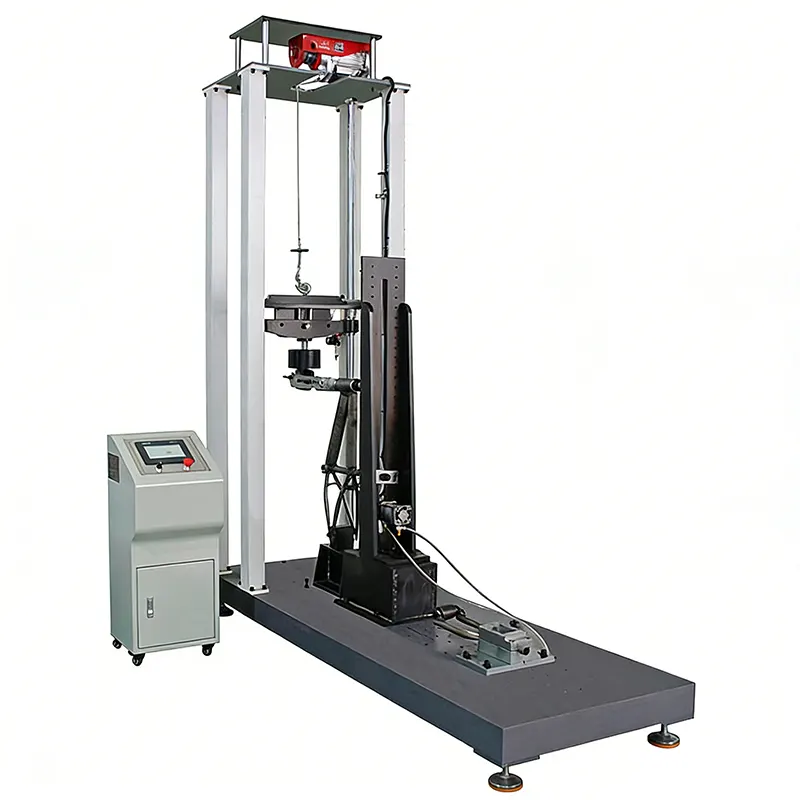
Conducting impact and drop tests requires specialized equipment with precise control over drop height, mass, and release mechanism. The Bicycle Impact and Drop Test Machine is designed specifically for these test procedures, with configurable parameters to cover all applicable standards.
The electromagnetic quick-release mechanism is a critical feature that many low-cost machines lack. A mechanical release (such as a rope pull or lever) introduces lateral forces and inconsistent timing that can affect test results by 10–15%. The electromagnetic release ensures that the mass falls straight down with minimal rotational impulse, producing repeatable results within ±2% of the calculated impact energy.
Step-by-Step Procedure
The following procedure describes the ISO 4210-3 fork drop test, which is the most commonly required impact test for bicycle manufacturers. The same machine, with different fixtures and parameters, can perform the frame impact and assembly drop tests.
Step 1: Specimen Preparation and Documentation
Select a production-representative fork specimen. No modifications or reinforcements are permitted. Before testing, document the following information: fork model, material (aluminum, carbon, steel, titanium), steerer tube diameter and wall thickness, blade cross-section type, and manufacturing batch number. Photograph the fork from at least four angles as a baseline reference.
Step 2: Mount the Fork in the Test Fixture
Install the fork in the test fixture with the steerer tube clamped securely in the vertical position. The fork must be oriented with the dropouts at the bottom and the crown facing the drop mass. Verify that the fork is aligned vertically using a digital level — any tilt exceeding 1° from vertical invalidates the test because it changes the impact force vector.
Step 3: Set Drop Parameters
Configure the machine for the applicable standard:
Step 4: Execute the Drop
Raise the test mass to the specified height. Verify the height using the machine’s digital readout (±2 mm accuracy). Activate the electromagnetic release. The mass falls freely and strikes the fork dropouts. The data acquisition system records the force-time curve at a minimum sampling rate of 10 kHz, capturing the peak impact force and impact duration (typically 5–15 ms for metal forks, 10–25 ms for carbon forks due to their greater compliance).
Step 5: Post-Impact Inspection
After the impact, carefully remove the fork from the fixture and conduct a thorough inspection:
- Visual inspection — Examine all surfaces under 10× magnification for cracks, especially at the crown-blade junction, dropouts, and steerer tube interface
- Deformation measurement — Measure the permanent set (residual deflection) at the dropout tips. The maximum allowable permanent set is typically 10 mm per ISO 4210
- Alignment check — Verify that the fork blades remain aligned and the dropout spacing has not changed by more than 2 mm
- Photography — Document the post-impact condition from the same four angles as the baseline
Step 6: Report and Analyze
Compile a comprehensive test report including the force-time curve, peak impact force, permanent deformation measurement, visual inspection findings, and a clear pass/fail determination. For carbon forks, include a tap test (acoustic resonance check) both before and after impact — a change in resonance frequency of more than 5% indicates internal delamination even if no surface cracks are visible.
Common Failure Modes
Understanding the most common failure modes observed during impact testing helps engineers design more robust frames and forks. The following analysis is based on data from over 300 impact tests conducted across multiple testing laboratories.
Carbon fiber forks present a unique challenge: internal delamination may not be visible from the surface, yet it can reduce the fork’s load-carrying capacity by 30–60%. This is why the tap test (acoustic resonance check) is essential for carbon components after impact testing. A fork that passes visual inspection but fails the tap test is unsafe and must not be returned to service.
Design Recommendations
Based on failure analysis data and industry best practices, the following design recommendations will improve impact test pass rates and real-world durability:
- Increase crown-blade junction wall thickness by 15–20% — This is the highest-stress area in the fork drop test. A localized reinforcement (gusset or thickened section) at the crown-blade transition reduces peak stress by approximately 25% without significantly affecting fork weight.
- Use butted steerer tubes — A steerer tube with a thicker wall at the lower end (near the crown) and a thinner wall at the upper end optimizes the strength-to-weight ratio. The lower steerer experiences the highest bending moment during impact.
- Specify minimum wall thickness for aluminum forks — Aluminum forks with blade wall thickness below 1.5 mm frequently fail the permanent deformation criterion. A minimum wall thickness of 1.8 mm at the blade midpoint provides adequate impact resistance for most riding categories.
- Optimize carbon fiber layup for impact resistance — Add ±45° fiber layers near the crown and dropout areas. These off-axis layers absorb impact energy through shear deformation rather than brittle fracture, significantly improving impact resistance without adding weight.
- Avoid sharp internal corners in crown design — A fillet radius of at least 3 mm at all internal corners reduces stress concentration during impact loading. Sharp corners act as crack initiation sites under high strain-rate loading.
- Test at least 3 specimens per model — Statistical confidence requires multiple samples. A single passing test does not guarantee production consistency. Test 3 specimens for standard models and 5 for critical safety components.
Frequently Asked Questions
Q1: What is the pass/fail criterion for the ISO 4210 fork drop test?
The fork must withstand the specified impact (22.5 kg from 600 mm for standard bicycles) without any visible cracks, fractures, or separation of components. Additionally, the permanent set (residual deflection) must not exceed 10 mm. Any visible crack, regardless of size, constitutes a test failure.
Q2: Can I use the same specimen for both impact and fatigue testing?
No. Impact testing is destructive — even if the specimen appears undamaged, the impact event introduces internal damage (especially in carbon fiber) that would invalidate subsequent fatigue test results. Each test requires a fresh, undamaged specimen.
Q3: How does e-bike impact testing differ from standard bicycle testing?
E-bikes are heavier than conventional bicycles, which means they generate higher impact forces in real-world drops. ISO 4210:2023 has updated the test mass requirements for e-bikes to account for the increased system weight. Additionally, the battery mounting area on the frame must withstand impact without damaging the battery enclosure, which is a separate test requirement under EN 15194.
Q4: What is the difference between the fork drop test and the frame impact test?
The fork drop test simulates a front-wheel impact by dropping a mass directly onto the fork dropouts, delivering high energy (132 J). The frame impact test simulates a localized strike on the frame by dropping a lighter mass from a lower height (22.5 kg from 125 mm = 27.6 J). The fork test evaluates overall fork strength; the frame test evaluates local dent resistance and crack initiation resistance.
Q5: How often should impact testing be performed on production bicycles?
Type approval testing (initial product certification) requires testing 3–5 specimens per model. For ongoing production, a statistical sampling plan should be implemented: test at least 1 complete set of specimens per 500 units produced, or whenever there is a change in material supplier, manufacturing process, or design specification.
Q6: Can a carbon fiber fork pass the ISO 4210 fork drop test?
Yes, many carbon fiber forks pass the standard 132 J fork drop test. However, carbon forks require careful design attention to the crown area, where the transition from the steerer tube to the fork blades creates high local stresses. The key is to use a mixed layup with ±45° plies in the crown region to absorb impact energy through shear rather than relying solely on 0° axial fibers that are prone to brittle fracture.
Q7: What does a typical force-time curve look like during a fork drop test?
The force-time curve shows a sharp rise to peak force (typically 5–15 kN for metal forks, 3–8 kN for carbon forks) within 1–3 ms, followed by a rapid decay with oscillations as the fork rebounds. The total impact duration is 5–15 ms for metal and 10–25 ms for carbon. A longer impact duration with lower peak force indicates better energy absorption, which is generally desirable for rider comfort and safety.
Q8: What equipment calibration is required for impact testing?
The drop height measurement system must be calibrated annually with a traceable length standard (±0.5 mm accuracy). The test masses must be verified annually using a calibrated scale (±10 g accuracy). If the machine includes a force measurement system (load cell), it must be calibrated per ISO 7500-1 annually. All calibration certificates must be maintained for ISO 17025 accreditation audits.
Q9: Are suspension forks tested differently than rigid forks?
Yes. Suspension forks are tested in the fully extended position (no rider weight compression) and with the suspension locked out if a lockout feature exists. The impact energy is the same, but the force-time curve is dramatically different — suspension forks show a much longer impact duration and lower peak force due to the damping effect. The pass/fail criteria remain the same (no visible cracks, permanent set ≤ 10 mm).
Q10: What happens if a fork fails the drop test during certification?
A failure during type approval testing means the bicycle cannot be sold in the target market until the design is modified and re-tested. Conduct a thorough failure analysis (fractography, material testing, FEA validation) to identify the root cause. Common fixes include increasing wall thickness at the failure location, adding a gusset at the crown-blade junction, or changing to a higher-strength material grade. After design changes, test at least 3 new specimens to confirm the fix.
Related Products
Need Professional Bicycle Testing Equipment?
Explore our range of testing machines designed for compliance with international standards.