Derui chamber
Selecting the right chassis dynamometer for two-wheeled electric vehicles is one of the most consequential decisions a testing laboratory or OEM manufacturer can make. Unlike four-wheeled vehicles, two-wheeled EVs present unique challenges in dynamometer testing: their lighter frames, higher center of gravity relative to track width, single-track dynamics, and regenerative braking systems all demand specialized equipment configurations. This buyer’s guide provides a comprehensive framework for evaluating, selecting, and implementing a chassis dynamometer system tailored to electric motorcycles, e-bikes, and electric scooters.
Key Takeaways
- ECE R.62, ISO 4209, and UN Regulation No. 78 set the mandatory safety and performance benchmarks for motorcycle frame and component testing.
- Fatigustandards-methods-and-best-practices/”>e testing protocols require a minimum of 100,000 load cycles at specified force magnitudes to simulate multi-year real-world usage.
- Drop impact testing evaluates frame integrity at defined heights — typically 300-500 mm — to simulate crash scenarios and curb impacts.
- Steering head strength and torsion tests verify handling stability under extreme cornering loads encountered in sport and adventure riding.
- Exhaust system durability testing ensures compliance with noise emission regulations and vibration resistance across 5,000+ hours of operation.
📑 Table of Contents
- ▸ What Is a Chassis Dynamometer for Two-Wheeled EVs?
- ▸ Key Specifications to Evaluate
- ▸ Roller Configuration and Wheel Restraint Systems
- ▸ Absorption Unit Types: Eddy Current vs AC/DC
- ▸ Regenerative Braking Testing Capability
- ▸ Data Acquisition and Control Systems
- ▸ Safety Features and Compliance
- ▸ Total Cost of Ownership
- ▸ Installation and Facility Requirements
- ▸ Top Manufacturers and Models
- ▸ FAQ: Buying a Two-Wheeled EV Chassis Dynamometer
What Is a Chassis Dynamometer for Two-Wheeled EVs?
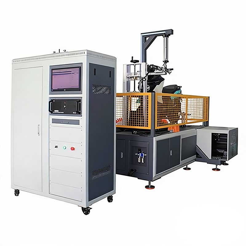
A chassis dynamometer (or “dyno”) is a testing platform that simulates real-world road conditions in a controlled laboratory environment. For two-wheeled electric vehicles, the dyno measures power output, torque curves, efficiency mapping, range estimation, and thermal behavior — all without the vehicle leaving the test cell. Unlike engine dynamometers that couple directly to the crankshaft, a chassis dyno drives the vehicle’s wheels on rollers, measuring performance at the wheel hub where the rubber meets the road.
Two-wheeled EV chassis dynamometers differ significantly from their automotive counterparts. The roller diameter must accommodate narrower tires (typically 80mm–130mm wide), the restraint system must safely hold a single-track vehicle upright under load, and the power absorption range must match the lower output of electric two-wheelers (typically 1 kW to 150 kW) while still capturing the instant torque characteristics of electric motors. Additionally, the dyno must handle bidirectional power flow — both absorbing energy during acceleration tests and accepting regenerated energy during deceleration.
Key Specifications to Evaluate
When comparing chassis dynamometer systems for two-wheeled EVs, several core specifications determine whether a particular unit will meet your testing requirements. These specifications interact with each other — a higher power absorption capacity may reduce measurement resolution at low loads, and larger roller diameters may limit maximum speed. Understanding these trade-offs is essential for making an informed purchase decision.
The right tier depends on your vehicle portfolio. If you primarily test e-bikes and low-speed scooters (under 25 km/h, Class 1–3 in EU regulations), an entry-level system with 20 kW absorption is typically sufficient. For electric motorcycles producing 50–150 kW and reaching speeds above 200 km/h, a high-end system with full bidirectional power flow becomes necessary. Mid-range systems are ideal for laboratories testing a mix of e-scooters, e-mopeds, and lower-performance electric motorcycles up to 11 kW continuous power.
Roller Configuration and Wheel Restraint Systems
The roller configuration is perhaps the most physically distinctive element of a two-wheeled EV dynamometer. Unlike car dynos with wide rollers, two-wheeled dynos use narrower rollers that must precisely contact the tire contact patch. The roller diameter directly affects test accuracy — smaller rollers create a tighter curvature that deforms the tire more, increasing rolling resistance and generating heat that doesn’t exist on flat road surfaces. Industry best practice recommends a minimum roller diameter of 300 mm for tire widths above 100 mm, and 400 mm or larger for high-speed testing above 150 km/h where tire deformation effects compound.
Single-Roller vs Dual-Roller Designs
Two primary roller configurations exist in the market. Single-roller (one-roller-per-axle) systems are the most common for two-wheeled EVs because they closely simulate flat-road contact, minimize tire wear, and provide the most accurate power measurements. The vehicle sits with one wheel on the roller and is restrained by a front or rear fixture. Dual-roller systems use two rollers per axle, cradling the wheel between them — this provides better vehicle stability but introduces parasitic losses at the second contact point and can affect measurement accuracy by 2–5%.
Wheel restraint is critical for safety and measurement repeatability. The most common approach uses a combination of a front wheel chock and a rear tie-down system with load cells. The chock fixes the steering axis, preventing lateral movement, while the rear restraint applies a controlled downward force to maintain tire-to-roller contact without overloading the suspension. Some premium systems use a pneumatic or servo-driven restraint that automatically adjusts clamping force based on the test load profile — this is particularly important for electric vehicles where the instant torque can cause wheel spin on the rollers if insufficient downward force is applied.
Absorption Unit Types: Eddy Current vs AC/DC
The power absorption unit (PAU) is the heart of any chassis dynamometer — it converts the vehicle’s mechanical output into a measurable resistive force. Three main PAU technologies are used in two-wheeled EV dynamometers, each with distinct advantages and limitations that directly impact test capabilities and operating costs.
Eddy current absorbers use electromagnetic fields to create drag on a rotating disc. They are the most affordable option, highly reliable with minimal maintenance, and provide excellent low-speed torque control. However, they cannot absorb regenerated energy — all energy is dissipated as heat — making them unsuitable for comprehensive EV testing where regenerative braking characterization is required. Eddy current systems typically handle steady-state and transient power tests well but cannot simulate road load driving cycles that include deceleration phases.
AC dynamometers (also called AC motor-based systems) use a synchronous or induction AC motor as both absorber and driver. They offer full bidirectional power flow, meaning they can absorb power during acceleration and drive the rollers during deceleration to simulate road load — essential for WLTP and EPA driving cycle testing of electric vehicles. AC systems can also feed regenerated energy back to the grid, reducing electricity costs by 30–50% in high-throughput labs. The trade-off is higher initial cost and more complex installation requiring a dedicated power supply.
DC dynamometers use a DC motor for power absorption and offer similar bidirectional capability to AC systems but with faster torque response times (typically under 5 ms vs 10–20 ms for AC). This faster response is valuable for capturing the extremely rapid torque transients of electric motors. DC systems are less common in new installations due to higher maintenance requirements (brush wear) and lower efficiency compared to AC systems, but they remain popular in retrofit applications.
Regenerative Braking Testing Capability
Regenerative braking is a defining feature of electric vehicles that fundamentally changes how chassis dynamometers must operate. When an EV decelerates, its motor acts as a generator, converting kinetic energy back into electrical energy that charges the battery. On a dynamometer, this means the PAU must either absorb this regenerated energy or actively drive the rollers to simulate the road load during deceleration. Without this capability, the dynamometer cannot accurately replicate real-world driving cycles such as WLTP Class 3, EPA Urban Dynamometer Driving Schedule (UDDS), or custom OEM drive cycles that include coast-down and braking phases.
For compliance testing under UN ECE R83 or EU Regulation 168/2013, a bidirectional dynamometer is mandatory because the test protocols include deceleration phases where the vehicle’s regenerative system is active. The dyno must be able to measure both the positive torque (driving) and negative torque (regeneration) with equivalent accuracy. This requires a four-quadrant operation mode where the PAU can seamlessly transition between motoring and absorbing without torque discontinuities. AC dynamometers with regenerative drives excel here, achieving transition times under 20 ms — fast enough to capture even the most aggressive regenerative braking events.
A critical but often overlooked aspect is the dyno’s ability to simulate vehicle inertia. Two-wheeled EVs range from 15 kg (e-scooters) to 400 kg (large electric motorcycles). The dynamometer must replicate this inertia range either mechanically (with flywheel sets) or electronically (with software-based inertia simulation). Electronic inertia simulation is preferred for EV testing because it allows continuous adjustment — essential when testing vehicles with varying battery states of charge that affect total vehicle mass.
Data Acquisition and Control Systems
The data acquisition (DAQ) system determines what you can measure, how accurately you can measure it, and how easily you can integrate test results into your engineering workflow. Modern two-wheeled EV dynamometers require DAQ systems capable of sampling at 1 kHz or higher to capture the fast transient behavior of electric motors — particularly the initial torque spike at zero speed that is characteristic of permanent magnet synchronous motors (PMSMs) used in most electric motorcycles.
Key measurement channels for EV testing include: wheel speed and roller speed (for slip detection), torque at the roller shaft, battery voltage and current (for energy consumption calculations), motor temperature, controller CAN bus data, and throttle position. The DAQ system should support CAN bus integration (J1939 or proprietary OEM protocols) to log motor controller parameters alongside dyno measurements — this is essential for correlating motor controller behavior with wheel-level performance.
Control system software should support automated test sequences: steady-state mapping (sweeping speed at fixed throttle positions), transient cycle testing (WLTP, EPA, custom), maximum power runs, and coast-down calibration. The ability to create custom test scripts is valuable for OEMs with proprietary test procedures. Look for systems that export data in standard formats (CSV, MATLAB .mat, MDF) and offer API access for integration with simulation tools like AVL CRUISE M or IPG CarMaker.
Safety Features and Compliance
Testing two-wheeled vehicles on a dynamometer inherently involves balancing an inherently unstable vehicle on rotating machinery. Safety is non-negotiable, and the dynamometer system must include multiple layers of protection. Primary safety features include emergency stop systems (both hardware e-stops and software-triggered shutdowns), wheel restraint monitoring with automatic test abort if restraint load drops below threshold, overspeed protection that disengages the PAU if roller speed exceeds limits, and fire suppression systems for the test cell.
For EV-specific testing, additional safety considerations apply. High-voltage battery systems (48V to 400V+) require the test cell to meet electrical safety standards including ISO 6469-1 (on-board rechargeable energy storage system protection) and IEC 62477-1 (power electronics converter systems safety). The dynamometer control system should interlock with the vehicle’s battery management system (BMS) to automatically shut down the test if the BMS reports a fault condition such as over-temperature, over-current, or cell voltage imbalance.
💡 Pro Tip: Always verify that the dynamometer’s emergency stop system independently cuts power to both the PAU and the vehicle’s throttle input. A common failure mode is the dyno e-stop killing the PAU but leaving the vehicle’s motor controller active — which can cause uncontrolled acceleration if the vehicle’s throttle is still engaged.
Total Cost of Ownership
The purchase price of a chassis dynamometer represents only 40–60% of its total cost of ownership over a 10-year period. When evaluating systems, consider the complete financial picture including installation costs, annual calibration, maintenance, consumables, and electricity. Installation alone can add $10,000–$50,000 depending on whether your facility needs structural reinforcement (dyno foundations require 200–400 mm reinforced concrete), electrical upgrades (AC dynamometers may need 3-phase 480V supply), and ventilation systems for tire and brake heat dissipation.
One significant cost factor unique to EV dynamometer testing is electricity consumption. AC regenerative dynamometers can recover 60–80% of the absorbed energy and feed it back to the grid, dramatically reducing operating costs for labs running 8+ hours per day. For a mid-range system running 2,000 hours annually, regenerative capability can save $5,000–$15,000 per year in electricity costs, often justifying the higher initial investment within 3–5 years.
Installation and Facility Requirements
Proper installation is critical for dynamometer accuracy and longevity. The dyno foundation must be isolated from building vibrations — even minor floor vibrations can introduce noise into torque measurements, especially at the low torque levels typical of e-bike testing (under 50 Nm). A proper foundation consists of a reinforced concrete pad (minimum 300 mm thick, 1.5x the dyno footprint) on vibration isolation pads, with the dyno bedplate anchored to the pad with precision leveling adjustments.
The test cell environment must also be controlled. Temperature stability within ±2°C is necessary for repeatable results, as tire pressure and roller surface friction both change with temperature. For EV testing, the cell must include adequate ventilation for battery thermal management — some high-power electric motorcycles can dissipate 5–10 kW of heat from the battery pack and motor during sustained full-load testing. A dedicated cooling air supply of 2,000–5,000 m³/h is recommended for high-power test cells.
Electrical infrastructure requirements vary by PAU type. Eddy current dynamometers typically need only single-phase 230V power for the control system and cooling fan. AC dynamometers require three-phase power (typically 380–480V) rated for the full absorption capacity plus a 20% margin. The main disconnect and circuit protection should be located within 3 meters of the dynamometer for emergency access. All electrical installations must comply with local codes and should be reviewed by a licensed electrical engineer.
Top Manufacturers and Models
The chassis dynamometer market for two-wheeled EVs has expanded significantly as electric vehicle production has grown. Several manufacturers now offer purpose-built systems for this segment. When evaluating manufacturers, consider not only the hardware specifications but also the depth of their application engineering support, the availability of local service technicians, spare parts lead times, and the maturity of their control software for EV-specific test protocols.
- DeRui Tester — Specializes in two-wheeled vehicle testing equipment with a dedicated chassis dynamometer line for electric motorcycles and scooters. Offers AC regenerative systems with CAN bus integration and custom drive cycle programming. Particularly strong in the Asian market with excellent local support infrastructure.
- AVL List GmbH — Industry leader with comprehensive dynamometer platforms. Their E-Motor test systems can be adapted for two-wheeled chassis testing. Premium pricing but unmatched software ecosystem (AVL PUMA, AVL CONCERTO) and global service network.
- Horiba — Offers the STARS platform with two-wheeled dynamometer configurations. Strong integration with emissions testing equipment, making them a good choice for labs that need both performance and regulatory compliance testing.
- Meidensha Corporation — Japanese manufacturer with extensive experience in EV dynamometer systems. Their AC regenerative dynos are known for high measurement accuracy (±0.2% torque) and excellent low-speed torque control.
FAQ: Buying a Two-Wheeled EV Chassis Dynamometer
1. Can I use a car chassis dynamometer for two-wheeled EV testing?
Technically possible but practically inadvisable. Car dynos have rollers that are too wide (typically 400–800 mm) and too large in diameter (often 500+ mm) for motorcycle tires, creating inconsistent contact patches and inaccurate power measurements. More critically, car dynos lack the wheel restraint systems needed to safely hold a two-wheeled vehicle upright under load. Retrofitting a car dyno for two-wheeled use typically costs 60–80% of a purpose-built system while delivering inferior results.
2. What is the minimum roller diameter I should consider?
For most two-wheeled EV applications, 300 mm is the minimum acceptable roller diameter. This provides a reasonable balance between measurement accuracy and physical footprint. If your testing includes vehicles with tire widths over 120 mm or speeds above 150 km/h, 400 mm rollers are strongly recommended. Below 250 mm, tire deformation effects introduce significant measurement errors that are difficult to correct mathematically.
3. Do I need a regenerative dynamometer for e-bike testing?
It depends on your test scope. If you only need maximum power and torque measurements, an eddy current system is sufficient. However, if you need to run driving cycle tests (WLTP, EPA, or custom), measure range and energy consumption, or characterize regenerative braking performance, a bidirectional AC or DC system is mandatory. For most OEMs and accredited test labs, the driving cycle capability justifies the additional cost.
4. How often should the dynamometer be calibrated?
Per ISO 9001 and most accreditation standards (ISO/IEC 17025), dynamometer calibration should be performed annually. However, torque transducers should be verified with reference weights monthly, and roller speed should be checked with a calibrated tachometer quarterly. After any mechanical maintenance (roller bearing replacement, PAU repair), a full calibration is required before resuming test operations.
5. What standards govern chassis dynamometer testing of two-wheeled EVs?
Key standards include ISO 13349 (industrial fans — dynamometer testing principles, often referenced for general dyno methodology), UN ECE R168 (approval of L-category vehicles with electric powertrain), EU Regulation 168/2013 (L-category vehicle type approval), WLTP Phase 1b (Worldwide Harmonized Light Vehicle Test Procedure adapted for L-category), and SAE J2908 (power rating method for automotive electric drive motor systems). Your dynamometer must comply with the measurement accuracy requirements specified in each applicable standard.
6. How do I handle vehicles with hub motors vs mid-drive motors?
Hub motor vehicles are straightforward — the motor output is measured directly at the wheel on the roller. Mid-drive motors that power the rear wheel through a chain or belt drive require careful attention to drivetrain efficiency losses. Most dynamometer software allows you to configure drivetrain loss parameters so that motor-level power can be calculated from wheel-level measurements. For the most accurate mid-drive motor characterization, consider an engine dynamometer that couples directly to the motor shaft, using the chassis dyno only for full-vehicle validation.
7. Can a single dynamometer test both e-scooters and electric motorcycles?
Yes, but with limitations. Mid-range systems with adjustable roller widths and restraint fixtures can accommodate wheelbases from 700 mm (e-scooters) to 1,600 mm (large motorcycles). The challenge is power range — an e-scooter producing 2 kW requires very different measurement sensitivity than an electric motorcycle producing 100 kW. Look for systems with dual-range torque transducers (e.g., 0–50 Nm and 0–500 Nm) that automatically switch ranges based on the vehicle being tested, maintaining ±0.5% accuracy across the full range.
8. What is the typical lead time from order to commissioning?
Standard systems typically require 8–16 weeks from order to delivery, with an additional 2–4 weeks for installation and commissioning. Custom configurations (special roller sizes, unique restraint systems, or non-standard power ranges) can extend this to 20–30 weeks. Plan your procurement timeline accordingly, especially if the dyno is needed for a specific homologation deadline. Some manufacturers maintain stock of popular configurations that can be delivered in 4–6 weeks.
9. How important is software for the overall testing workflow?
Extremely important. The control software is your primary interface with the dynamometer and directly impacts test efficiency, data quality, and operator training time. Modern systems should offer automated test sequencing, real-time data visualization, integrated road load simulation (coast-down coefficient application), and seamless data export. Poor software can turn a capable hardware platform into a frustrating experience — always request a live software demonstration before purchasing.
10. What warranty and service coverage should I expect?
Standard warranty periods range from 12 to 24 months. Look for manufacturers that offer extended warranty options and guaranteed response times for on-site service (typically 24–48 hours for critical failures). Remote diagnostics capability is increasingly important — modern systems should support VPN-based remote access so the manufacturer’s engineers can troubleshoot and often resolve issues without a site visit. Spare parts availability is also critical; confirm that commonly replaced items (bearings, seals, torque transducers) are stocked locally with delivery within 48 hours.
Related Products
Need Professional Motorcycle Testing Equipment?
Explore our range of testing machines designed for compliance with international standards.