Derui chamber
What Is a Chassis Dynamometer?
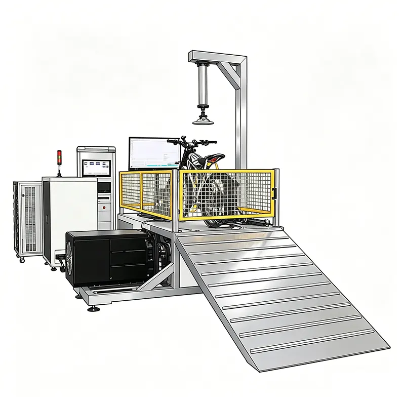
A chassis dynamometer, commonly referred to as a chassis dyno, is a precision testing instrument that measures the power, torque, speed, and energy consumption of a vehicle at its drive wheels. Unlike an engine dynamometer—which measures output directly at the crankshaft—a chassis dynamometer evaluates the complete drivetrain system, including the motor, transmission, controller, and wheel assembly. For two-wheeled electric vehicles (e-bikes, e-scooters, and electric motorcycles), this distinction is critical because the overall efficiency of the powertrain, including regenerative braking and battery management, can only be assessed when the vehicle is tested as an integrated system on the road or on a chassis dyno that simulates road conditions.
Key Takeaways
- ECE R.62, ISO 4209, and UN Regulation No. 78 set the mandatory safety and performance benchmarks for motorcycle frame and component testing.
- Fatigue testing protocols require a minimum of 100,000 load cycles at specified force magnitudes to simulate multi-year real-world usage.
- Drop impact testing evaluates frame integrity at defined heights — typically 300-500 mm — to simulate crash scenarios and curb impacts.
- Steering head strength and torsion tests verify handling stability under extreme cornering loads encountered in sport and adventure riding.
- Exhaust system durability testing ensures compliance with noise emission regulations and vibration resistance across 5,000+ hours of operation.
The principle of operation is straightforward yet sophisticated. The vehicle’s drive wheel sits on a set of motorized or electromechanically braked rollers. As the wheel spins the rollers, the dynamometer applies a controlled resistance—known as the load—that simulates aerodynamic drag, rolling resistance, and gradient climbing. Sensors embedded in the roller assembly measure torque and rotational speed, which are then used to compute power output and energy draw from the battery pack. Modern chassis dynamometers for two-wheelers typically use eddy-current brakes or AC permanent-magnet motors operating in regenerative mode to absorb power and provide precise, repeatable loading profiles.
For manufacturers and testing laboratories, the chassis dynamometer serves as the backbone of type approval testing, R&D benchmarking, quality control on production lines, and after-sales diagnostic work. Standards such as UN ECE R85 (measurement of net power of electric engines), ISO 7118 (motorcycle test methods), and GB/T 24157 (electric motorcycle range and energy consumption tests in China) all reference chassis dynamometer testing as the preferred or mandatory method for verifying performance claims.
📑 Table of Contents
Key Components of a Two-Wheeler Chassis Dynamometer
Understanding the architecture of a chassis dynamometer helps engineers select the right system for their application and troubleshoot calibration issues. A typical two-wheeler chassis dyno consists of the following major subsystems:
Roller Assembly
The rollers are the physical interface between the test vehicle and the dynamometer. For two-wheeled vehicles, most chassis dynos use a single large-diameter roller (typically 400–600 mm) or a twin-roller configuration where two smaller rollers support the tire from below. Single-roller designs reduce tire deformation and provide more accurate speed measurement, while twin-roller setups are easier for the operator to mount the vehicle. The roller surface may be knurled or coated with a high-friction material to prevent tire slippage under high-torque conditions. Roller diameter directly influences the tire contact patch and the effective rolling radius, so the dynamometer software must account for this when computing true road speed from roller RPM.
Absorption Unit (Brake)
The absorption unit is the heart of the dynamometer’s loading capability. Two technologies dominate the market:
- Eddy-current brake: Uses an electromagnetically induced current in a rotor disc to create resistance. Eddy-current brakes offer excellent low-speed torque, fast response time, and require no external cooling water in low-power configurations. However, they cannot generate power (they only absorb), meaning they cannot simulate downhill conditions or regenerative braking energy recovery.
- AC/DC motor (regenerative): An electric motor connected to the roller shaft can operate in motoring mode (spinning the roller to simulate downhill or coasting) or generating mode (absorbing vehicle power and feeding it back to the grid). This bidirectional capability makes AC-motor dynos ideal for testing regenerative braking systems, which are standard on most electric two-wheelers. The downside is higher cost and more complex drive electronics.
Measurement and Control System
The control system integrates a torque transducer (typically a strain-gauge-based load cell or a non-contact torque sensor on the roller shaft), a speed encoder (optical or magnetic, with resolution of 100–1000 pulses per revolution), a power analyzer (for measuring battery voltage and current), and a data acquisition unit. Modern systems use an industrial PC or PLC running specialized software that implements standardized test cycles—such as the WMTC (World Motorcycle Test Cycle) for emission-type testing or custom constant-speed discharge profiles for range validation. The software computes road-load coefficients (A, B, C) from coast-down tests and applies them as the simulated resistance during steady-state or transient testing.
Fixturing and Safety Systems
Two-wheeled vehicles are inherently unstable when stationary. The dynamometer must include front and rear tie-down straps or a hydraulic/electric clamping system that secures the vehicle frame without distorting the suspension. A side-support stand or drop-down stabilizer wheels prevent the vehicle from tipping laterally during high-speed or high-torque testing. Additionally, an emergency-stop button, a motor-current limiter, and an over-temperature protection circuit are mandatory safety features per ISO and IEC machine-safety standards.
Setup Procedure: Step-by-Step Guide
Proper setup is the foundation of accurate and repeatable dynamometer test results. Skipping or rushing any of the following steps will introduce measurement errors that are difficult to diagnose later.
Step 1: Pre-Test Inspection
Before placing the vehicle on the dynamometer, conduct a thorough pre-test inspection. Verify that tire pressure matches the manufacturer’s recommended value (typically 2.0–2.5 bar for e-scooters, 2.5–3.5 bar for electric motorcycles). Under-inflated tires increase rolling resistance and produce artificially high energy consumption figures, while over-inflated tires reduce the contact patch and may cause slippage on the rollers. Check the drive chain or belt tension, brake pad clearance (dragging brakes add parasitic load), and confirm that the battery is at the specified state of charge—usually 100% SOC for range tests or a defined level for performance tests per the applicable standard.
Step 2: Vehicle Mounting
Roll the vehicle onto the dynamometer rollers and align the rear tire so that it is centered on the roller surface. For single-roller configurations, use the built-in wheel chocks or guide rails to prevent lateral movement. Attach the tie-down straps to the frame (never to the swingarm or suspension components) and apply sufficient tension to prevent the vehicle from lifting off the front wheel under heavy acceleration. The front wheel should be either chocked or allowed to rest on a low-friction turntable—some dynamometers include a front-wheel platform that measures steering forces during stability tests.
Step 3: Connection and Wiring
Connect the high-voltage power measurement probes to the battery pack terminals or to the motor controller input/output as required by the test specification. Use calibrated current clamps (Hall-effect sensors) with appropriate range for the expected current (typically 50–300 A for e-scooters, 100–600 A for electric motorcycles). Install a thermocouple or RTD sensor on the battery case and on the motor housing to monitor temperature throughout the test. Connect the CAN bus adapter if the dynamometer system needs to read real-time vehicle telemetry (battery SOC, motor RPM, controller status). Ensure all wiring is secured away from rotating parts and that the cooling fan (if used) is positioned to simulate realistic airflow over the motor and controller at the target test speed.
Step 4: Software Configuration
Launch the dynamometer control software and create a new test session. Enter the vehicle specifications: curb mass (kg), test mass (including rider and cargo if applicable), tire specification, roller diameter, and target test cycle (e.g., WMTC Part 1, constant 40 km/h discharge, UDDS cycle). Configure the data logging parameters—sampling rate should be at least 10 Hz for transient cycles, with channels for roller speed, roller torque, battery voltage, battery current, power, cumulative energy, and temperature. Set the safety interlock limits: maximum roller speed (km/h), maximum torque (Nm), maximum test duration (minutes), and over-temperature thresholds.
Calibration Methods and Standards
Calibration is the process of verifying that the dynamometer’s torque, speed, and force measurements agree with traceable national or international standards. Without regular calibration, test results are meaningless—and in the context of regulatory type approval, non-calibrated equipment renders the test invalid.
Torque Calibration
Torque is calibrated by applying known moments to the roller shaft using a calibrated lever arm and precision weights or a reference torque transducer. The procedure is straightforward: a lever of known length (e.g., 500 mm) is attached perpendicular to the roller shaft. Certified calibration weights (traceable to SI units via NIST, PTB, or equivalent national metrology institutes) are placed on the lever at a known distance from the shaft centerline. The resulting torque (T = F × d, where F is force in Newtons and d is distance in meters) is compared against the dynamometer’s torque reading. This is repeated at a minimum of five points across the measurement range (e.g., 0%, 20%, 40%, 60%, 80%, and 100% of maximum torque). The tolerance per ISO 9001 and most automotive test standards is typically ±1% of reading or ±0.5 Nm, whichever is greater.
Speed Calibration
Speed calibration is performed by driving the rollers at known speeds using the dynamometer’s own motoring function (if equipped) and comparing the displayed speed against a reference tachometer with traceable calibration. The reference tachometer is typically an optical encoder or laser-based non-contact sensor that counts the revolutions of the roller surface directly. Alternatively, a handheld tachometer strobe can be used to verify roller RPM at several setpoints. The acceptable tolerance is generally ±0.5% of reading for emission and energy-consumption testing per UN ECE R85 and GB/T 24157.
Coast-Down and Parasitic Loss Calibration
Before every test series, the dynamometer’s inherent mechanical losses—bearing friction, windage, and encoder drag—must be characterized through a coast-down calibration. With no vehicle on the rollers, the control system accelerates the rollers to the maximum test speed and then disengages all loading. The rollers decelerate due to internal friction alone. The control software records the deceleration rate at multiple speed points and generates a parasitic loss curve that is automatically subtracted from the vehicle’s measured power during subsequent tests. This curve should be verified at least weekly or whenever a test session begins. Failure to perform coast-down calibration will result in the dynamometer over-reporting the vehicle’s actual power output.
Common Test Cycles and Applications
Chassis dynamometer testing for two-wheeled EVs serves multiple purposes, from regulatory compliance to R&D optimization.
Range and Energy Consumption Testing
Range testing is the most widely performed chassis dyno test for electric two-wheelers. The vehicle is fully charged to 100% SOC, mounted on the dynamometer, and driven through a standardized driving cycle until the battery is depleted or the vehicle’s BMS cuts power. The cumulative energy consumed (in Wh) is divided by the distance covered (in km) to yield the energy consumption rate (Wh/km). Key standards include GB/T 24157-2017 (China), UN ECE R85 (International), WMTC (World Motorcycle Test Cycle), and ECE R68 (maximum speed measurement).
Regenerative Braking Performance
For electric two-wheelers equipped with regenerative braking, the chassis dynamometer provides the only controlled environment for measuring braking energy recovery efficiency. The test procedure involves accelerating the vehicle to a specified speed, then applying the regenerative braking function and measuring the power fed back into the battery. Metrics of interest include the regenerative braking efficiency (percentage of kinetic energy recovered), the braking force vs. deceleration curve, and the transition smoothness between regenerative and mechanical braking. This data is essential for optimizing the BMS algorithm and for meeting the stopping-distance requirements of ECE R78.
Thermal Validation and Durability
Repeated acceleration-deceleration cycles on the chassis dyno simulate real-world thermal stress on the motor, controller, and battery. Manufacturers use extended dyno runs—often 500–1000 km equivalent—to validate thermal management performance, identify hot-spot issues, and verify that the BMS thermal protection thresholds operate correctly. Thermocouples attached to the stator windings, MOSFET heatsinks, and individual battery cells provide the temperature data needed to build thermal models and derating curves. This type of testing is critical for vehicles sold in hot climates where ambient temperatures regularly exceed 40°C.
Troubleshooting Common Setup Issues
Even experienced operators encounter problems during dynamometer testing. Here are the most common issues, their root causes, and corrective actions:
Maintenance and Care Guidelines
A chassis dynamometer is a significant capital investment, and proper maintenance ensures consistent accuracy and long service life:
- Daily: Visual inspection of rollers for damage or debris. Verify that all safety interlocks are functional. Run a no-load coast-down check and compare the results to the baseline curve. Clean the roller surface with a dry cloth.
- Weekly: Verify speed calibration with a reference tachometer at three speeds (25%, 50%, 75% of max). Check tie-down strap condition and replace if frayed or stretched. Inspect electrical connections for tightness and corrosion.
- Monthly: Perform full torque calibration with certified weights. Verify force transducer calibration. Check bearing temperatures under load and listen for unusual noises. Update control software if patches are available.
- Annually: Commission a full calibration by an accredited third-party laboratory (ISO 17025). Replace roller bearings if radial play exceeds 0.05 mm. Service the absorption unit (eddy-current brake air gap adjustment or AC motor bearing replacement).
Pro Tip: Always record the coast-down curve and calibration data after each maintenance session. Comparing these records over time provides early warning of bearing wear, brake deterioration, or encoder drift—issues that are invisible during routine testing but will silently degrade measurement accuracy.
How to Choose the Right Dynamometer for Your Application
Selecting a chassis dynamometer requires matching the system’s specifications to your testing requirements. Key decision factors include:
- Maximum power absorption: E-scooters typically require 5–15 kW, while electric motorcycles may need 50–200 kW. Choose a dynamometer with at least 20% headroom above your maximum expected power to avoid operating near the absorption unit’s limit, where accuracy degrades.
- Maximum speed: Most e-scooters are tested at speeds up to 60–80 km/h, while electric motorcycles may reach 120–180 km/h. Ensure the roller assembly is rated for the maximum speed with an appropriate safety margin (typically +10%).
- Bidirectional capability: If regenerative braking testing is required, an AC-motor-based dynamometer is essential. Eddy-current-only systems cannot simulate downhill conditions or measure energy recovery.
- Software and automation: Look for a system that supports the test cycles you need (WMTC, GB/T, custom profiles), offers automated test sequencing, and provides comprehensive data export (CSV, raw binary, and report-ready formats).
- Footprint and infrastructure: Consider the laboratory floor space, power supply requirements (typically 380V three-phase for high-power systems), cooling water supply (for water-cooled eddy-current brakes), and ventilation for heat dissipation.
Frequently Asked Questions
What is the difference between an engine dyno and a chassis dyno?
An engine dynamometer measures power at the crankshaft by directly coupling to the engine output. A chassis dynamometer measures power at the drive wheels, reflecting the efficiency of the entire drivetrain (motor, controller, transmission, chain/belt, and tire). For electric two-wheelers, chassis dynos are preferred because they evaluate the complete powertrain as it operates in the vehicle, including losses from the reduction gear, chain drive, and tire deformation.
How often should a chassis dynamometer be calibrated?
Full torque and speed calibration by an accredited laboratory should be performed annually. Internal verification checks (using certified weights and a reference tachometer) should be conducted monthly. The no-load coast-down curve, which characterizes parasitic losses, should be verified at the start of every test session or at least weekly.
Can a chassis dynamometer test both e-scooters and electric motorcycles?
Yes, provided the dynamometer’s power absorption capacity and maximum speed rating cover both vehicle types. Some manufacturers offer multi-purpose systems with interchangeable fixture kits that accommodate different wheel sizes, tire widths, and vehicle weights. However, using a 200 kW motorcycle dynamometer to test a 1 kW e-scooter may result in poor resolution at low torque values, so consider a dual-range system or a dedicated low-power unit if you test both regularly.
What is a coast-down test and why is it necessary?
A coast-down test characterizes the dynamometer’s internal mechanical losses by measuring how quickly the rollers decelerate from a high speed to rest with no vehicle loaded. The resulting loss curve is subtracted from subsequent test data to ensure that the measured torque and power values reflect only the vehicle’s output, not the dynamometer’s own friction and windage. Without this correction, test results would be artificially low.
How does tire pressure affect dynamometer test results?
Tire pressure has a significant impact on rolling resistance. Under-inflated tires deform more at the roller contact patch, increasing friction and drag, which leads to higher measured energy consumption and lower apparent range. Over-inflated tires reduce the contact area, potentially causing slippage and speed-measurement errors. Always use the vehicle manufacturer’s recommended tire pressure and verify it before each test session.
Can regenerative braking be tested on an eddy-current dynamometer?
No. Eddy-current brakes can only absorb energy—they cannot return energy to the grid or simulate the vehicle’s inertia during deceleration. Testing regenerative braking requires a dynamometer with an AC motor that can operate in motoring mode to drive the rollers during the braking phase. Some advanced systems combine eddy-current absorption for steady-state loading with a small AC motor for transient inertia simulation, but a fully regenerative AC system is the most capable solution.
What safety precautions are essential for dynamometer operation?
Key safety measures include: secure the vehicle with rated tie-down straps before every test; never stand beside the vehicle during high-speed operation; verify that the emergency-stop system is functional before each session; keep loose clothing, tools, and cables away from rotating components; ensure adequate ventilation to prevent accumulation of battery off-gas in the event of a thermal event; and always follow the lockout/tagout procedure when performing maintenance on the roller assembly or absorption unit.
What is the typical cost of a two-wheeler chassis dynamometer?
Prices vary widely based on specifications. A basic e-scooter dynamometer with eddy-current absorption (5–15 kW) typically costs USD 15,000–30,000. A mid-range system suitable for electric motorcycles (50–100 kW) with AC regenerative capability ranges from USD 40,000–80,000. High-end systems used by OEM R&D centers (150–200 kW, fully automated, with environmental chamber integration) can exceed USD 150,000. Installation, commissioning, and training typically add 10–20% to the base price.
Related Products
Need Professional motorcycle testing Equipment?
Explore our range of testing machines designed for compliance with international standards.