Derui chamber
Motorcycle Test Bench Selection Guide: Dyno, Frame, Brake and Wheel Systems
One motorcycle testing project can involve four very different stations. Match each rig to the decision it must support, the specimen it must hold and the evidence your team needs before asking for a quotation.
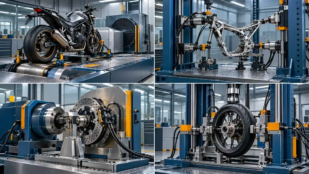
A chassis dynamometer measures an operating motorcycle or drive system. A frame rig loads a structure. A brake station evaluates braking under the conditions defined by its method. A wheel rig tests a wheel with its own support and loading arrangement. Select each by required output and boundary condition; do not treat these stations as interchangeable.
“Motorcycle test bench” is useful as a search term, but it is too broad for an equipment specification. A supplier could respond with a roller dyno, a frame vibration rig, a brake tester or a wheel fatigue machine. All may be valuable. Only one may answer the immediate engineering question.
This guide is for a manufacturer, component supplier or laboratory planning a test capability. It connects test decisions to station types and then to the information needed in an RFQ. It is a selection framework, not a list of universal force, speed or accuracy settings; those depend on the motorcycle, test method and target market.
Choose the station by the decision the test must support
Start with one sentence: What will we decide from this result? An R&D team may compare design changes; a production team may screen vehicles; a component supplier may investigate wheel fatigue; a compliance team may need evidence for a defined vehicle category and market. These decisions lead to different specimens, fixtures and measurement channels.
| Test question | Likely station | Critical interface | Evidence to request |
|---|---|---|---|
| How does the motorcycle or drive system perform under a defined operating load? | Chassis roller dyno or separate powertrain dyno | Wheel/roller contact or motor output coupling, plus cooling and safety | Speed, torque or power channels; programmed load; repeatable run record |
| How does the frame respond to cyclic load or vibration? | Frame vibration or fatigue rig | Frame mounting, load application points and specimen clearance | Load or acceleration history, cycle count, fixture drawing, failure stop |
| Does the braking system meet the chosen test outcome? | Vehicle-level brake test arrangement or component station | Brake input, vehicle/wheel motion and measuring location | Method-specific speed, brake input and response record |
| Does the wheel satisfy its defined strength or durability method? | Wheel/rim test rig | Hub, axle, rim and load path | Applied load/torque history, cycles, setup and defect record |
Selection rule: The test name on a brochure does not prove that a rig covers a particular regulation or customer method. Ask the supplier for a method-to-fixture-to-measurement matrix and a representative factory acceptance demonstration.
Chassis and powertrain dynos: define what is being driven
A chassis dynamometer operates the assembled motorcycle through its driven wheel on a roller. A motor or powertrain dyno connects closer to the component output. Both can collect speed, torque and power-related data, but they include different losses, interfaces and safety considerations. A component dyno result should not be presented as if it were a whole-vehicle result.
For a chassis project, provide wheel and tyre sizes, vehicle mass range, wheelbase, target operating points and how the motorcycle will be secured. State whether the programme needs steady operating points, acceleration, a controlled load sequence or endurance running. For an electric motorcycle, identify the electrical channels and thermal or cooling conditions required by the test decision. Each extra channel should have a clear purpose.
Derui has a dedicated electric motorcycle test bench product page. Treat its published description as a starting point for discussion and request a configuration matched to your vehicle and method.
Frame rigs: distinguish vibration response from fatigue life
A frame vibration test and a fatigue test may use some similar hardware, yet they ask different questions. Vibration work may examine a response to a defined excitation. Fatigue work applies repeated loads and monitors the specimen over cycles. Their fixture stiffness, sensors, control logic and stop conditions may differ. The required procedure must be identified before the actuator and platform are chosen.
Supply frame drawings and show where the machine may restrain the structure. Mark the intended force or excitation points, the largest expected displacement and any areas that must stay accessible for inspection. If multiple motorcycle frames will share a rig, give the complete geometry range, not one representative model. Check that fixture changeover preserves alignment and the intended load path.
For an example of a dedicated equipment direction, review the motorcycle frame vibration test machine. Before purchase, compare its proposed configuration with your own controlled procedure and sample geometry.
Brake systems: separate vehicle approval tests from component endurance
Motorcycle brake testing spans vehicle-level braking performance and component-level development or durability. Those are not the same test. A component station may repeatedly actuate a lever or caliper. A vehicle-level method can require a defined vehicle condition, test surface, speed and measured braking outcome. The equipment must reflect the result required by the selected procedure.
UN Regulation No. 78 concerns approval of specified L-category vehicles with regard to braking. Its scope helps identify the regulatory route for applicable vehicles, but a bench alone does not confer approval. For a project using that route, first confirm the vehicle category and current applicable text, then list the exact tests and measurements needed. State separately any internal brake endurance sequence the lab also wants to run.
- Define whether the specimen is an assembled motorcycle, wheel/brake assembly or isolated component.
- Identify front/rear brake configuration, ABS or combined braking where relevant.
- State how brake input and vehicle or wheel response will be measured.
- Record the method, test conditions, sequence and acceptance decision for each task.
Wheel rigs: match the wheel material and test method
Wheel durability is not a single universal machine function. ISO 8644:2006 addresses test methods for light-alloy road wheels for motorcycles within its scope. It should not be assumed to cover every spoked, steel or other wheel design. Confirm the wheel construction and the actual method before specifying a radial, torsional or impact arrangement.
The hub or axle interface is often as important as the load unit. Send hub drawings, wheel sizes, tyre conditions if relevant and the proposed loading direction. Ask how the rig maintains alignment, detects a change in response and records the condition at test stop. If several wheel families share equipment, identify the adapters and revalidation steps required at changeover.
Derui’s motorcycle wheel torsional fatigue tester illustrates one specialist station. It should be evaluated against your wheel design and controlled procedure rather than treated as a universal wheel tester.
Plan the laboratory in phases, based on throughput and risk
A laboratory with one high-volume production check may benefit from a dedicated station and quick fixture changeover. An R&D laboratory may value a configurable platform, more measurement channels and easier access to raw data. A supplier qualification lab may need fixtures that make results comparable across parts and factories. These choices affect staffing, floor space and operating cost as much as the purchase price.
| Phase | Decision | Document to approve |
|---|---|---|
| 1. Define methods | Which tests must be run in-house and which can be outsourced? | Test list with specimen, method, edition and acceptance decision |
| 2. Group compatible work | Which tasks can genuinely share controls, sensors or utilities? | Station coverage matrix with explicit exclusions |
| 3. Fix the interfaces | Will all target specimens fit and mount reproducibly? | Fixture concept and sample envelope drawing |
| 4. Agree acceptance | How will the supplier prove the proposed station meets the RFQ? | FAT plan using representative specimen and measured criteria |
Sharing a controller does not guarantee that fixtures, actuation or results can be shared. Make every claimed multi-method capability visible in the coverage matrix. For acceptance planning, our test equipment FAT checklist gives a practical review structure.
Motorcycle test bench RFQ: information worth sending first
A useful enquiry lets an engineer identify the right station before proposing a price.
- Motorcycle type, target market, vehicle category and representative drawings.
- Test purpose and acceptance decision for each item.
- Applicable regulation, standard edition, customer method or internal procedure.
- Specimen geometry, mass range and mounting or coupling interface.
- For dynos: required speed/load operating points, cooling and data channels.
- For frame rigs: load or vibration points, fixture boundary conditions and failure stop logic.
- For brakes: vehicle-level versus component-level scope and measured response.
- For wheels: construction, hub interface, method and loading direction.
- Production volume, changeover expectations, available utilities and space.
- Raw data, report format, calibration evidence and representative FAT test.
If multiple station types are needed, ask for a phased quotation showing each station, shared utilities, exclusions and acceptance criteria separately.
Need a motorcycle testing lab configuration?
Send Derui your test list, vehicle or component drawings and target methods. Our team can review the dyno, frame, brake and wheel tasks, then discuss which stations and fixtures belong in your first procurement phase.