Derui chamber
Product & Technical
Load, Stroke and Cycle Requirements for Fatigue Test Machines: An RFQ Guide
A fatigue test machine should be specified from the method and the specimen, not from the biggest force number in a brochure. Load, stroke and cycle requirements only become meaningful after you define what the test must prove.
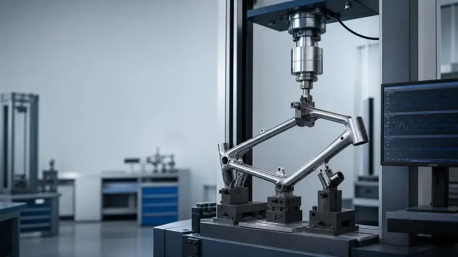
Start with the applicable test clause and the product classification. Then define the specimen geometry, the required control mode, the normal operating range, the overload boundary, the cycle profile, the stop conditions and the measurements you need to record. A fatigue machine that is oversized, underspecified or based on the wrong control mode can still fail the project even if its maximum load looks impressive.
Many RFQs ask for “one 5 kN fatigue tester” or “one 100,000-cycle machine” before the project team has described what the actuator must control, how far the sample must move, where the load enters the structure or what counts as a failure. That approach usually causes one of two problems: either the quoted machine is too generic to reproduce the method, or the quoted machine includes expensive capacity that never improves the quality of the result.
Start with the Engineering Decision
Before discussing load, stroke or cycle count, write one sentence that starts with: “This test will determine whether…” That sentence forces the project team to define the decision behind the machine purchase. Are you comparing two designs in R&D? Demonstrating conformity to a standard? Running incoming inspection? Screening finished goods in production? These use cases can involve the same specimen but still require different machine architecture.
Official standards overviews show why this matters. ISO 4210-6:2023 covers frame and fork test methods for the bicycle requirements in ISO 4210-2. BSI’s public overview of BS EN 15194 shows that EPAC bicycles include requirements and test methods for power management and electrical systems as well as the mechanical product. BSI’s overview of BS EN 17128 similarly shows that PLEV projects sit inside a wider safety framework, not a single frame test. The machine therefore has to answer the right project question, not just apply force repeatedly.
Defining the Required Load Range and Application Point
Load should be defined as an operating envelope, not a headline number. Start by identifying the commanded input required by the method: force, torque, bending moment, displacement-derived load or a road-simulation input converted through a fixture. Then record the normal working range, the highest expected transient or overload, the acceptable control tolerance and the sensor resolution needed at the normal operating point.
A common mistake is choosing a much larger load cell “for safety.” That may protect the hardware, but it can reduce usable resolution where the real test happens. If most of the project runs in a low or medium range, define the primary measurement quality in that range first. Then confirm overload protection separately.
Record the normal test load band where you expect the machine to spend most of its time. This is the range that matters most for control stability and data quality.
Record the largest credible transient, setup mistake or proof load the machine must survive without damaging the actuator, fixture or sensor chain.
The requirement is not only “reach 2 kN.” It is also “hold 2 kN within the acceptable tolerance at the required frequency and waveform.”
The same force number can create a different structural response if the lever arm, contact point, support condition or fixture stiffness changes.
Defining Actuator Stroke and Travel
Stroke is often misunderstood as total actuator travel available from the machine. For fatigue planning, the more useful definition is the required controlled travel during the real test, including ramp-in, pre-load, specimen deformation, fixture compliance, safety margin and setup adjustment. If you only specify the specimen displacement and forget fixture movement or alignment space, the selected stroke may be technically large but still impractical.
Stroke also depends on the control mode. In a force-controlled fatigue test, the actuator may need extra travel to maintain force as the sample relaxes or deforms over time. In a displacement-controlled test, the commanded movement itself may be the acceptance-critical variable. That is why the RFQ should state not just stroke magnitude, but also whether the stroke is sinusoidal, triangular, ramp-hold, block-programmed or method-specific.
| Stroke input | What to define | Why it matters |
|---|---|---|
| Controlled motion | Peak-to-peak or one-way movement required by the test method | Determines the practical working stroke for the actuator and controller |
| Fixture compliance | Movement consumed by grips, levers, adapters and support structures | Prevents undersizing when the specimen is not the only moving element |
| Alignment and setup margin | Space needed for installation, preload and safe travel limits | Makes the machine easier to use across multiple sample variants |
| End-of-life behaviour | Expected deformation growth or sudden release near failure | Helps define stop logic and mechanical protection |
Building the Fatigue Cycle Program
Cycle count alone is not enough. The machine specification should define the full cycle requirement: waveform, frequency range, hold time, rest interval, program blocks, target total cycles, inspection checkpoints and event-based stop conditions. A request for “100,000 cycles” is incomplete if it does not say whether those cycles are run at one fixed amplitude, in multiple blocks, with dwell periods, at different frequencies or until a measurement threshold changes.
Think of cycle definition as a sequence design problem. For example, one project may require a constant-amplitude fatigue block followed by a proof load and a final dimensional inspection. Another may require alternating high and low load blocks to simulate service use. The machine controller, data logger and safety logic have to support the real sequence, not just a raw counter.
Define whether the cycles are sinusoidal, square, triangular or custom. The waveform changes actuator demand and specimen response.
Define the normal operating frequency and any upper limit allowed by the method or specimen heating behaviour.
State whether all cycles are identical or whether the sequence changes by block, level or event trigger.
Define when the test should pause for visual checks, dimensional checks, torque checks or electrical verification.
Selecting the Appropriate Control Mode
Some fatigue projects are fundamentally force-controlled. Others are displacement-controlled, torque-controlled or speed-controlled. A fatigue rig that is excellent in one control mode may be inefficient or unstable in another. This is one of the most expensive specification mistakes because it changes the actuator, sensor chain, software logic and fixture assumptions together.
Use the standards route and specimen behaviour to decide the control priority. ISO 4210-6 shows that bicycle frame and fork work is defined through formal test methods rather than generic machine classes. BSI’s public overviews of EN 15194 and EN 17128 likewise show that the test programme belongs to a structured product route. The practical inference is that the control mode must match the method and evidence requirement, not just the easiest parameter for a supplier to quote.
| Control mode | Best fit | Main RFQ question |
|---|---|---|
| Force control | When the method defines an applied force envelope | Can the machine maintain the required force accurately across the real frequency range? |
| Displacement control | When specimen motion is the commanded variable | Can the actuator reach and repeat the required travel without losing stability near specimen softening? |
| Torque control | When rotating joints, stems or drive components are evaluated | Is torque measured and controlled at the right location and with the right fixture stiffness? |
| Speed or profile control | When the method depends on motion speed, roller speed or drive-cycle simulation | Does the sequence logic match the actual service profile and stop conditions? |
Translating Test Requirements into an RFQ
If you want a useful quotation, package the method and the specimen before asking for the machine. Derui’s related content, such as What Testing Equipment Does My Industry Need?, works best when it leads into a clause-based RFQ rather than a short equipment wish list.
Fatigue Test Machine RFQ Checklist
- Product type and intended use
- Applicable standard edition or customer method
- Clause list or test matrix
- Sample drawings, photos or CAD files
- Normal load range and overload boundary
- Required stroke and installation margin
- Cycle waveform, frequency and total sequence
- Control mode priority
- Sensor outputs and report requirements
- Stop logic, safety interlocks and FAT evidence
Frequently asked questions
Should I choose the biggest load capacity available?
No. Capacity should cover the real operating range and credible overloads, but resolution and control quality at the normal test point matter more than an oversized headline number.
Can one fatigue machine cover many products?
Often yes, if the base frame, actuator and control system cover the envelope and the fixtures are configurable. The RFQ still has to define the largest, smallest and most demanding sample variants clearly.
What is the most common RFQ mistake?
Sending only a force value and target cycle count. Without control mode, stroke logic, fixture geometry and acceptance requirements, the quotation is usually incomplete or misleading.
Why does the fixture matter so much?
The fixture defines how the load enters the sample. A correct actuator with the wrong boundary condition can produce results that look repeatable but do not represent the method or the real service load path.
Need help defining a fatigue test machine specification?
Send Derui your sample drawing, method clause list, target loads, stroke logic and required measurements. We can help turn that into a usable machine specification, fixture concept and FAT checklist before quotation.
Sources and note
- ISO 4210-6:2023, frame and fork test methods abstract.
- BSI overview of BS EN 15194:2017+A2:2023, EPAC scope and requirements summary.
- BSI overview of BS EN 17128:2020, PLEV scope and requirements summary.
This article is a practical specification guide. Numeric test parameters, tolerances and pass or fail criteria must come from the current licensed standard, approved customer method or agreed laboratory procedure.