Derui chamber
Bicycle Brake Testing Guide
Bicycle Brake Testing: Procedure, Equipment and Result Review
A reliable bicycle brake test connects the applicable method to a controlled specimen, repeatable operating condition, verified measurements and documented acceptance criteria.
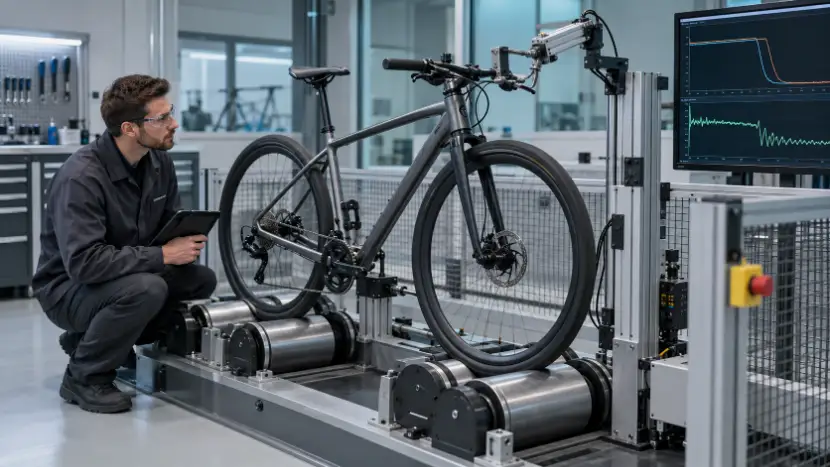
Bicycle brake testing is more than applying a lever and observing whether the wheel slows. The result depends on product classification, specimen preparation, brake adjustment, operating condition, control of the input, measurement timing and the acceptance rule. If any of these changes between specimens, apparent product variation may actually come from the test process.
This guide explains how to translate a controlled brake test method into an equipment and laboratory workflow. It deliberately does not reproduce proprietary tables, forces, speeds or acceptance values. Those details should be taken from the applicable standard edition and the approved internal test plan.
Confirm Product Scope and the Applicable Method
Identify the bicycle type, intended use, target market and any exclusions before preparing the bench. ISO 4210-2:2023 covers requirements for specified bicycle categories, while specialized bicycles may follow other requirements. E-bikes may also have product-specific requirements beyond the conventional bicycle brake method. Classification is therefore an engineering input, not an assumption made by the operator.
Record the complete reference for every controlled document: standard number, part, edition, amendment or corrigendum where applicable, and the internal procedure revision. ISO states that ISO 4210-4:2023 specifies braking test methods for ISO 4210-2. This relationship matters: the requirements and the method are separate documents and should be reviewed together.
Extract the required specimen condition, brake configuration, operating method, measurements and acceptance criteria into a test plan. When a customer procedure modifies a published method, identify each difference rather than describing the test only as “ISO compliant.”
Define What the Test Equipment Must Control and Measure
The test architecture depends on the selected method. It may involve a complete bicycle on a controlled surface or roller system, brake-actuation equipment, speed or distance measurement, force measurement and data acquisition. The bench must reproduce the method without introducing unintended restraint or changing normal brake operation.
| Function | Equipment question | Evidence to retain |
|---|---|---|
| Bicycle support | Does restraint preserve the required operating condition and alignment? | Fixture setup and approved position |
| Brake actuation | Is the specified input applied at the correct interface and direction? | Actuator or force-channel verification |
| Operating condition | Can speed, distance, load or other method variable be controlled? | Recorded sequence and actual values |
| Performance measurement | Are the required values measured in the correct interval? | Raw or calculated result with units |
| Safety and stop logic | What condition stops the test without losing failure evidence? | Alarm and event record |
Select sensors for the useful measurement range, not only their maximum rating. Define calibration status, zero checks and channel verification before the first specimen. The software should show the operator the approved recipe and capture actual results, not merely display a live graph.
Prepare the Bicycle and Brake System Consistently
Log the bicycle identity, category, size, mass where required, wheel and tyre configuration, brake type, control interface and relevant component identifiers. Inspect the specimen for transport damage or previous use that could affect the result. Record any allowed conditioning or adjustment.
Brake setup must follow the controlled method and product instructions. Cable tension, hydraulic condition, pad or shoe position, rotor or rim condition, tyre condition and fastener security can influence the result. Do not quietly correct an abnormal specimen after testing begins; document the observation and follow the approved deviation or retest process.
Where bedding, conditioning or warm-up is required, keep it separate from the measured sequence and document its completion. A consistent preparation record makes later failure analysis far more useful.
Set Up and Verify the Test Bench
Install the bicycle using approved datums and fixtures. Verify wheel alignment, contact condition, clearance, cable routing and access to the brake control. The fixture should prevent unsafe movement without adding a structural path that changes the test result.
Connect and identify each measurement channel. Confirm units, zero, direction and expected signal response. Load the correct recipe using the bicycle identity or a controlled manual selection. Before the full sequence, use a safe verification step to confirm rotation, actuation direction, data capture and stop functions.
Run the Controlled Test Sequence
Follow the approved order of operations. A typical workflow includes an initial condition check, controlled operation, application of the specified brake input, measurement during the defined interval, release or recovery, and any required repeated or subsequent stage. The exact sequence comes from the applicable method.
Monitor actual values rather than assuming the command was achieved. Record interruptions, limit events, fixture movement, unusual sound, heat, leakage or visible change. If the method allows operator observations, use controlled descriptions rather than free-form conclusions.
Stop logic should protect the operator and equipment while preserving the information needed to understand a failure. Define emergency stops, normal completion, out-of-limit stops and specimen-failure stops separately. Retesting after an interrupted run requires an approved rule because prior brake operation may have changed the specimen.
Review Results, Variation and Failure Evidence
Compare results with the acceptance criteria from the controlled requirement document. Keep the measured values and calculation method with the pass/fail decision. A result close to a limit may justify a review of uncertainty, setup and repeatability, but it should not be reclassified informally.
When results differ unexpectedly, check the full measurement chain before blaming the product. Review specimen preparation, recipe revision, fixture alignment, brake input, operating condition, sensor zero, calibration status and calculation window. Compare curves and event timing where available.
| Observation | Product-related possibility | Test-system check |
|---|---|---|
| Low or inconsistent response | Adjustment, friction interface or component condition | Input application, contact condition and measurement timing |
| Asymmetric behavior | Component alignment or assembly variation | Bicycle position, roller alignment and fixture influence |
| Signal drift | Changing product condition | Zero stability, temperature influence and channel integrity |
| Unexpected stop | Real failure or limit event | Stop threshold, noise and interlock history |
Preserve photographs and failed parts when investigation is required. A useful failure record states what happened, when it occurred and which signals support the conclusion. It should distinguish confirmed facts from hypotheses.
Build a Traceable Test Record
The report should identify the specimen, product category, brake configuration, controlled documents, equipment, fixtures, sensors, calibration status, preparation, environmental or operating conditions where required, sequence, results, deviations and acceptance decision. Include the responsible operator and reviewer.
Link the report to raw data or protected result files according to the laboratory quality system. When software calculates a final value, retain the method and relevant input channels. Record any retest with the original result and authorization rather than replacing the first record.
Brake Test Preparation Checklist
- Confirmed bicycle classification and target market
- Current controlled requirements and method editions
- Approved test plan and acceptance criteria
- Specimen identity and brake configuration
- Documented conditioning and adjustment
- Verified fixture, alignment and contact condition
- Correct recipe and operator permissions
- Calibrated measurement channels
- Confirmed units, zero and signal direction
- Verified brake-actuation interface
- Test sequence and stop logic checked
- Result, observation and deviation fields prepared
If a laboratory needs a broader bicycle equipment programme, review Derui’s bicycle and frame testing equipment category and the bicycle test bench selection guide. Equipment selection should remain tied to the actual controlled method and specimen range.
Need to configure a bicycle brake test system?
Send Derui the applicable method, bicycle drawings, brake configuration, required operating conditions, measurement channels and reporting needs. Our team can review the test workflow and prepare a technical configuration for discussion.
Primary standards references
ISO 4210-4:2023 specifies braking test methods for ISO 4210-2. ISO 4210-2:2023 specifies safety and performance requirements for the bicycle categories in its scope. Consult the official documents for controlled requirements, parameters and acceptance criteria.