Derui chamber
Electric scooter frames endure continuous vibration stress during daily operation—from uneven road surfaces, speed bumps, and repetitive loading cycles. Over time, these vibrations can initiate micro-cracks that propagate into catastrophic frame failures, posing serious safety risks to riders. Scooter frame vibration testing for fatigue life is therefore a critical quality control procedure that every manufacturer must implement before products reach the market. This comprehensive guide examines the testing standards, equipment specifications, and practical methodologies that define how scooter frames are validated for long-term durability under realistic vibration conditions.
Key Takeaways
- UL 2272 and EN 17128 are the primary safety standards governing e-scooter electrical and mechanical performance testing requirements.
- Frame fatigue testing for e-scooters requires higher impact energy levels compared to conventional bicycles due to additional battery and motor mass.
- Tire, wheel, and axle endurance tests simulate real-world urban riding conditions across varied road surfaces and loading scenarios.
- Brake system testing evaluates both mechanical and regenerative braking efficiency under dry and wet conditions per applicable standards.
- Environmental testing (IP rating, temperature cycling) ensures e-scooter safety across diverse operating climates and weather conditions.
📑 Table of Contents
- ▸ Why Vibration Testing Matters for Scooter Frames
- ▸ Key Standards for Scooter Frame Vibration Testing
- ▸ How Scooter Frame Vibration Test Machines Work
- ▸ Test Parameters and Configuration
- ▸ Fatigue Life Prediction from Vibration Data
- ▸ Common Failure Modes Detected by Vibration Testing
- ▸ Step-by-Step Vibration Test Procedure
- ▸ Equipment Specifications and Selection Criteria
- ▸ FAQ: Scooter Frame Vibration Testing
Why Vibration Testing Matters for Scooter Frames
Scooter frames operate in a dynamic vibration environment that is fundamentally different from static loading conditions. When a rider navigates urban terrain, the frame absorbs thousands of micro-impacts per kilometer—from cobblestone surfaces, expansion joints, pothole edges, and curb transitions. Each of these events transmits vibrational energy through the frame structure, concentrating stress at geometric discontinuities such as weld joints, tube junctions, and mounting points.
The critical concern with vibration-induced fatigue is that failures often occur at stress levels far below the material’s yield strength. A scooter frame might easily support a 150 kg static load without deformation, yet fail after 50,000 vibration cycles at a fraction of that load. This phenomenon—high-cycle fatigue—accounts for approximately 80-90% of all structural failures in metallic components according to research published in the International Journal of Fatigue. For aluminum alloy frames commonly used in e-scooters (6061-T6 and 6063-T5), the fatigue limit is typically only 30-40% of the ultimate tensile strength, making vibration testing indispensable.
Regulatory bodies worldwide recognize this risk. The European standard EN 17128:2020 explicitly requires vibration testing for personal light electric vehicles (PLEVs), while EN 14619 mandates fatigue validation for kick scooters. In the United States, ASTM F2264 addresses similar requirements for foot-propelled scooters, and UL 2272 incorporates vibration endurance as part of its electrical system safety assessment. Manufacturers who skip vibration testing face not only regulatory non-compliance but also significant liability exposure from field failures that could result in rider injuries.
Key Standards for Scooter Frame Vibration Testing
Multiple international standards govern scooter frame vibration testing, each targeting specific vehicle categories and performance expectations. Understanding which standard applies to your product is the first step toward compliance and market access.
EN 17128:2020 — Personal Light Electric Vehicles
EN 17128 is the primary European standard for e-scooters and other personal light electric vehicles with a maximum speed of 25 km/h. Section 5.4 of the standard specifies vibration testing requirements for the frame and steering assembly. The test involves mounting the scooter on a vibration table with a simulated rider mass (typically 100 kg) and subjecting it to a defined vibration profile. The standard requires that the frame withstand a minimum of 100,000 cycles without visible cracks, fracture, or loss of structural integrity. The vibration frequency range is specified between 5 Hz and 30 Hz, with acceleration amplitudes calibrated to simulate real-world road conditions.
EN 14619:2019 — Kick Scooters
EN 14619 covers non-motorized kick scooters and includes frame fatigue requirements that differ from those in EN 17128. The standard specifies a static fatigue test on the steering tube and frame assembly, with test forces calculated based on the scooter’s maximum rider weight rating. For scooters rated at 100 kg, the test force is typically 700 N applied cyclically for 50,000 cycles. While EN 14619 focuses more on static cyclic loading than pure vibration, many manufacturers combine both approaches to achieve comprehensive validation.
ASTM F2264-16 — Consumer Scooters (US Market)
ASTM F2264 is the American standard for foot-propelled scooters. It defines frame fatigue testing using a three-point bending configuration with cyclic loading. The test load is typically 1.5× the maximum rider weight, applied at a rate of 1-3 Hz for a minimum of 10,000 cycles. Although this standard predates the e-scooter boom, its principles are frequently referenced in US product liability cases, making compliance a practical necessity for manufacturers targeting the American market.
How Scooter Frame Vibration Test Machines Work
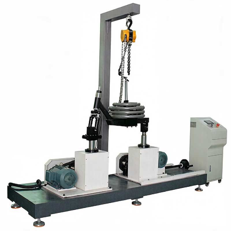
A scooter frame vibration test machine operates by mounting the complete scooter frame assembly onto a rigid test fixture that is bolted to an electromagnetic or servo-hydraulic shaker table. The shaker generates controlled vibration profiles that simulate the dynamic loads experienced during real-world riding conditions. Understanding the mechanics of these systems is essential for selecting the right equipment and interpreting test results accurately.
Electromagnetic Shaker Systems
Electromagnetic shakers are the most common type used in scooter frame vibration testing. They work by passing an alternating current through a coil suspended in a magnetic field, generating a force proportional to the current. Modern systems use digital signal processors (DSPs) to generate precise vibration waveforms—sine sweeps, random vibration, and composite profiles that replicate measured road data. The force output typically ranges from 1 kN to 20 kN, with frequency coverage from 5 Hz to 3,000 Hz. For scooter frame testing, the operating range is concentrated in the 5-100 Hz band where structural resonances and road-induced vibrations are most damaging.
Servo-Hydraulic Systems
Servo-hydraulic test systems offer higher force capacities (up to 100 kN or more) and are preferred when testing larger scooter frames or when combined static-dynamic loading is required. These systems use a hydraulic actuator controlled by a servo valve, with closed-loop feedback from load cells and displacement transducers. While they offer superior low-frequency performance (below 5 Hz) and higher force output, they have limited high-frequency capability compared to electromagnetic shakers, typically maxing out around 200-500 Hz. For pure vibration fatigue testing of scooter frames, electromagnetic systems are generally more suitable due to their broader frequency range and better waveform fidelity.
Fixture Design and Mounting
The test fixture is arguably the most critical component of the vibration test setup. It must rigidly secure the scooter frame to the shaker table while allowing vibration energy to transmit through the frame in a manner consistent with real-world loading. Poor fixture design can introduce spurious resonances, dampen critical vibration modes, or create stress concentrations at clamp points that produce misleading failure locations. Best practice involves using fixture materials with high stiffness-to-weight ratios (such as aluminum tooling plate or magnesium alloys), incorporating damping treatments to suppress fixture resonances, and validating the fixture with a bare frame run before testing begins.
Test Parameters and Configuration
Proper configuration of test parameters is essential for producing meaningful and reproducible results. The primary parameters include vibration frequency, acceleration amplitude, test duration, and loading conditions. Each parameter must be carefully selected based on the applicable standard and the intended use profile of the scooter.
Vibration Frequency and Sweep Profiles
Frequency selection determines which structural modes of the frame are excited during testing. Sine sweep testing—where the vibration frequency is gradually increased and decreased across a defined range—is the most common approach for fatigue life evaluation. For scooter frames, the sweep typically covers 5-30 Hz per EN 17128, with sweep rates of 0.5-2 octaves per minute. Random vibration testing, which simultaneously excites all frequencies within a specified bandwidth according to a power spectral density (PSD) profile, provides a more realistic simulation of road conditions but requires more sophisticated control systems. The PSD profile for urban scooter use typically shows peak energy between 8-20 Hz, corresponding to the first bending mode of most scooter frame geometries.
Acceleration Levels and Loading
The acceleration amplitude directly determines the stress levels induced in the frame. EN 17128 specifies acceleration levels calibrated to produce equivalent fatigue damage to real-world riding over the scooter’s expected service life. Typical test acceleration levels range from 1.5 g to 4.0 g RMS, depending on the scooter class and intended use. A simulated rider mass (usually 75-100 kg in the form of steel weights or sandbags) is mounted on the frame to replicate the inertial loading that occurs during actual riding. The combined effect of vibration and static mass loading creates stress patterns that closely match those observed in field-operated scooters.
Fatigue Life Prediction from Vibration Data
Vibration testing generates a wealth of data that can be used not only for pass/fail compliance but also for predicting the actual service life of scooter frames. The S-N curve (Wöhler curve) approach remains the industry standard for fatigue life prediction. This method relates the stress amplitude (S) to the number of cycles to failure (N), providing a characteristic curve for each material and joint configuration.
For scooter frame applications, the S-N curve is typically constructed from test data at multiple stress levels. A minimum of five stress levels with at least three specimens per level is recommended for statistical reliability. The data is fitted to a power-law relationship: N × S^m = C, where m is the slope parameter (typically 3-5 for aluminum welds) and C is a material constant. This relationship allows engineers to predict the fatigue life at any stress level within the valid range, enabling design optimization without excessive physical testing.
Miner’s linear damage accumulation rule is used to estimate fatigue life under variable-amplitude loading conditions representative of real-world use. The rule states that the total fatigue damage D equals the sum of the damage fractions at each stress level: D = Σ(ni/Ni), where ni is the number of cycles at stress level i and Ni is the number of cycles to failure at that level. Failure is predicted when D reaches 1.0, though conservative designs often use D = 0.5 as the acceptance criterion. Advanced methods such as the Palmgren-Miner modification and rain-flow counting algorithms improve prediction accuracy for complex vibration profiles.
Key Insight: For aluminum alloy scooter frames, the fatigue endurance limit (the stress level below which fatigue failure does not occur) is approximately 60-80 MPa for 6061-T6 welds. Frames designed with maximum operating stresses below this threshold theoretically have infinite fatigue life—though in practice, a minimum design life of 300,000 cycles is typically targeted.
Common Failure Modes Detected by Vibration Testing
Vibration testing reveals failure modes that static testing cannot detect. Understanding these failure patterns helps manufacturers improve frame designs and welding processes. The following are the most commonly observed failure modes in scooter frame vibration fatigue testing:
- Weld Toe Cracking: The most prevalent failure mode, accounting for approximately 60-70% of all vibration fatigue failures. Cracks initiate at the weld toe—the junction between the weld bead and the base material—where stress concentration factors can reach 2.0-3.5× the nominal stress. The heat-affected zone (HAZ) adjacent to the weld typically has reduced fatigue strength compared to the parent material, making it the weakest link in the frame structure.
- Steering Tube Junction Failure: The joint between the steering tube and the main frame deck experiences complex bending and torsional loads during vibration. Failures at this location often appear as circumferential cracks around the steering tube, propagating from the toe of the connecting weld. This failure mode is particularly dangerous because it can lead to sudden loss of steering control.
- Deck-to-Frame Weld Cracking: The deck platform experiences out-of-plane bending during vibration, creating peel stresses at the deck-to-frame welds. Cracks typically initiate at the weld ends and propagate along the weld length. The severity of this failure mode increases with deck width and rider weight.
- Folding Mechanism Fatigue: For folding scooters, the hinge mechanism and its mounting points are critical fatigue locations. Vibration testing frequently reveals loosening of hinge fasteners, cracking of hinge pins, and fatigue failure of the hinge mounting welds. This is a particular concern for shared scooter fleets that undergo frequent folding/unfolding cycles combined with vibration exposure.
- Battery Mount Point Failure: E-scooters with under-deck battery compartments have additional stress concentrations at the battery mounting points. Vibration-induced cracking at these locations can compromise both structural integrity and battery security, creating a compound safety risk.
Step-by-Step Vibration Test Procedure
Executing a compliant vibration test requires meticulous preparation and adherence to standardized procedures. The following step-by-step process outlines the complete test workflow from specimen preparation through final reporting.
- Specimen Selection and Preparation: Select a minimum of three scooter frames from the production line (not prototypes). Visually inspect each frame for surface defects, weld quality issues, and dimensional compliance. Mark all weld joints and critical locations with reference numbers for traceability. Record the frame serial number, production date, and material certification.
- Pre-Test Measurement: Measure and record the natural frequency of each frame using a modal hammer or low-level random vibration sweep. This baseline measurement identifies the frame’s resonant frequencies and mode shapes, which will be monitored throughout the test for indications of progressive damage.
- Fixture Installation: Mount the scooter frame onto the vibration test fixture using the production-standard axle mounting points. Apply the specified torque values to all fasteners and record the torque values. Install the simulated rider mass at the designated location on the deck platform.
- Instrumentation Setup: Attach accelerometers at a minimum of four locations: the shaker table reference point, the steering head, the deck center, and the rear wheel mount. Connect strain gauges at critical weld locations identified during the pre-test measurement phase. Verify all sensor calibrations and signal paths.
- Vibration Profile Programming: Program the vibration controller with the required test profile per the applicable standard. For EN 17128, this is typically a sine sweep between 5-30 Hz at the specified acceleration level. Run a low-level verification sweep (10% of test level) to confirm the setup is functioning correctly and there are no fixture resonances interfering with the test.
- Test Execution: Begin the full-level vibration test. Monitor acceleration levels, strain gauge readings, and natural frequency shifts in real-time. Automated crack detection systems (such as acoustic emission sensors) can provide early warning of crack initiation. Continue the test until the required number of cycles is completed or a failure is detected.
- Post-Test Inspection: After test completion, perform a thorough visual inspection of all weld joints and critical areas using 10× magnification. Perform dye penetrant or magnetic particle inspection on all welds to detect surface cracks not visible to the naked eye. Compare post-test natural frequency measurements with pre-test values—a frequency shift greater than 5% indicates structural degradation even if no visible cracks are present.
- Report Generation: Document all test parameters, measurements, observations, and results in a formal test report. Include photographs of the test setup, any observed failures, and the pre/post natural frequency comparison. The report must clearly state whether the specimen passed or failed the acceptance criteria defined by the applicable standard.
Equipment Specifications and Selection Criteria
Selecting the right vibration test equipment is a significant investment decision that impacts testing accuracy, throughput, and long-term operational costs. The following specifications represent the minimum requirements for a scooter frame vibration test system capable of meeting EN 17128 and related standards.
When evaluating vibration test equipment suppliers, prioritize systems with proven track records in two-wheeler testing applications. The controller software should support multiple test modes (sine, random, shock, and mixed-mode) with real-time monitoring and automated abort capabilities. Integration with strain gauge measurement systems and acoustic emission sensors adds significant value for research and development applications beyond basic compliance testing. Consider also the availability of local technical support, spare parts inventory, and calibration services—all of which impact long-term cost of ownership and testing uptime.
Related Products
- ▸ Scooter Frame Vibration Test Machine
- ▸ Scooter Dynamic Durability Test Machine
- ▸ Electric Scooter Tire Road Condition Testing Machine
Need Professional E-Scooter Equipment?
Explore our range of testing machines designed for compliance with international standards.
FAQ: Scooter Frame Vibration Testing
Q1: What is the minimum number of test specimens required for vibration fatigue testing?
EN 17128 requires a minimum of three specimens from the production line for type testing. For statistical validation or research purposes, five or more specimens per configuration are recommended. All specimens must be representative of the production process, not hand-built prototypes.
Q2: Can vibration testing be combined with other fatigue tests?
Yes, many manufacturers combine vibration testing with static cyclic fatigue tests to achieve comprehensive validation. However, each test must be performed on separate specimens—a frame that has undergone static fatigue testing cannot be used for vibration testing, as the accumulated damage would invalidate the results. Combined test protocols should be documented in the test plan and agreed upon with the certifying body.
Q3: How long does a typical scooter frame vibration test take?
A standard EN 17128 vibration test at 100,000 cycles with a sweep rate of 1 octave per minute over a 5-30 Hz range typically takes 12-24 hours depending on the specific profile configuration. Including setup, pre-test measurements, and post-test inspection, the complete process requires 2-3 working days per specimen batch.
Q4: What acceleration level should I use for testing beyond the standard minimum?
For accelerated testing or premium product validation, acceleration levels of 3.0-4.0 g RMS are commonly used. However, care must be taken to ensure that the increased stress does not shift the failure mode from high-cycle fatigue (the relevant mechanism) to low-cycle fatigue or yielding, which would produce non-representative results. A good rule of thumb is to not exceed 2× the standard test acceleration level.
Q5: Do I need to test the complete scooter or just the frame?
EN 17128 specifies testing of the frame and steering assembly as a complete unit, including the steering column, handlebar stem, and folding mechanism (if applicable). The wheels and motor may be excluded if they are independently tested. Testing the assembled unit ensures that interaction effects between components are captured—something that isolated frame testing cannot reveal.
Q6: How do I detect cracks during vibration testing without stopping the test?
Acoustic emission (AE) sensors are the most effective method for real-time crack detection during vibration testing. AE sensors detect the high-frequency stress waves emitted when a crack initiates or propagates, allowing the test to continue while monitoring for damage. A sudden increase in AE event rate or energy typically indicates crack initiation. Natural frequency monitoring provides a secondary detection method—a drop in resonant frequency of 5% or more indicates significant structural degradation.
Q7: What is the difference between sine sweep and random vibration testing?
Sine sweep testing excites one frequency at a time, sweeping through the specified range at a controlled rate. It is effective for identifying resonant frequencies and characterizing mode shapes, and is the method specified by EN 17128. Random vibration testing simultaneously excites all frequencies within a bandwidth according to a power spectral density profile, providing a more realistic simulation of actual road vibration but requiring more sophisticated control equipment. Many test labs use sine sweep for compliance testing and random vibration for research and development.
Q8: Can I use FEA (Finite Element Analysis) to replace physical vibration testing?
FEA is a valuable tool for design optimization and can predict stress distribution and natural frequencies with good accuracy. However, no current standard accepts FEA as a complete replacement for physical vibration testing. FEA can reduce the number of physical test iterations by identifying and eliminating weak designs before testing, but final compliance validation must be performed on physical specimens. Some certification bodies may accept a reduced physical test program when supported by validated FEA models, but this must be negotiated on a case-by-case basis.
Q9: What happens if a frame fails the vibration test?
If a frame fails, the failure must be thoroughly analyzed to determine the root cause. Common corrective actions include improving weld quality (profile control, defect elimination), increasing material thickness at high-stress locations, adding gussets or reinforcing ribs, and optimizing joint geometry to reduce stress concentration factors. After implementing corrective actions, the modified design must be re-tested. It is common for 2-3 design iterations to be required before achieving compliance.
Q10: How should I maintain my vibration test equipment for consistent results?
Regular maintenance is essential for test accuracy and repeatability. Key maintenance tasks include annual calibration of accelerometers and load cells (traceable to national standards), verification of shaker table flatness and stiffness every six months, inspection and replacement of fixture hardware every 1,000 test hours, and software updates per the manufacturer’s schedule. Environmental control of the test laboratory (temperature ±2°C, humidity 40-60% RH) is also critical, as aluminum fatigue properties are temperature-sensitive and sensor performance can drift with humidity changes.